Project Information
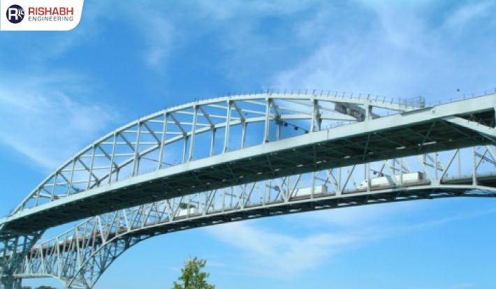
Pedestrian Bridge 3d Modeling Using Tekla Structures
Description
Client
A renowned Canada-based specialist in steel Fabrication & Infrastructure Projects from technological structures and structural warehouses to bridges & culverts with a state-of-the-art fabrication shop, they catered to the needs of modern automated machines adapted with advanced material management, production & planning tools.
Engineering Requirement
For their end customer, the client was looking for an engineering design partner to help them revamp the pedestrian bridge’s structural design to accommodate an appropriate pathway. Appointed as the engineering design services partner, our job was to provide recommendations with 3D models, structural fabrication drawings & material take-offs (MTOs) to propose the layout for the pathway. It was while establishing the detailed connection modeling (for bolted connection & railing details)
Backed by advanced modeling tools and sophisticated software, the overall scope for this project included the following;
- 3D modeling as per received input.
- Modeling & Drawing Extraction through advanced features of the Tekla model.
- Fabrication drawing. (Assembly, single part, GA & Erection).
- Detailed Connection modeling includes Bolted connection, bolt length, and hole diagram
- Customize railing detail.
- MTOs
Want to know more about this project?
Our Recent Projects

Connect with us for all your engineering design needs
US Toll-Free Phone
+1-877-747-4224
India Phone
+91 8511122697
Drop Us An Email
sales@rishabheng.com
Our Offices
USA, UK & India (Head office)
Ready to work with us? Tell us more
Our Recent blogs