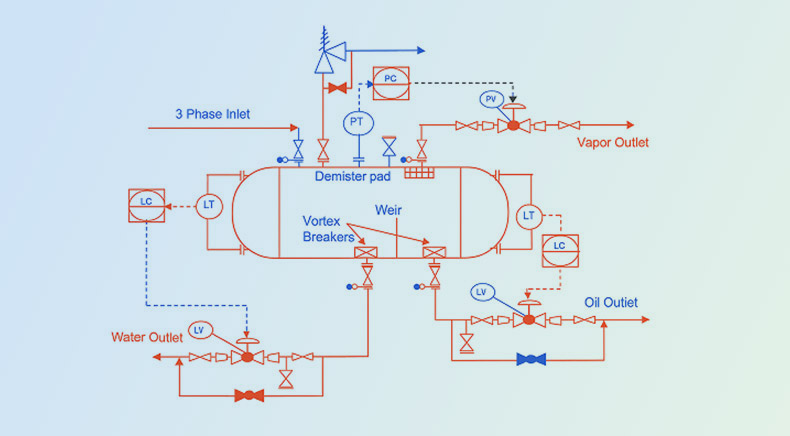
P&ID instrumentation symbols are the standardized visual language used to represent measuring instruments, control devices, signal types, and process control loops in industrial facilities. These symbols enable engineers, operators, and maintenance teams to interpret complex process information consistently across engineering disciplines, minimizing errors during design, construction, commissioning, and plant operations. The ANSI/ISA 5.1-2024 – Instrumentation Symbols and Identification standard establishes globally recognized conventions for instrument symbols, identification tags, and control system documentation, ensuring uniformity across industries such as oil & gas, chemicals, power generation, pharmaceuticals, and manufacturing.
This blog will dive deep into P&ID instrument symbols, explaining what they are, their importance, components, the types of symbols used, and how to interpret them and how Rishabh Pro Engineering integrates these standards to ensure efficient, safe, and compliant designs for process systems.
What Are P&ID Instrumentation Symbols?
P&ID instrument symbols represent the devices used in process control systems. These devices measure, control, and monitor process variables like pressure, temperature, flow, level, and others.
The instrumentation symbols in P&ID diagram are standardized graphical representations, often based on widely recognized codes such as ISA-5.1 (International Society of Automation), ISO 14617, or IEC standards.
P&ID instrument symbols serve several important purposes:
- Communication: By providing a clear, unambiguous picture of instruments and their link to the system, they help engineers, operators, and maintenance teams communicate effectively.
- Clarity in Design: Instrumentation symbols help identify possible areas for improvements or modifications by specifying how the control system will communicate with the process.
- Troubleshooting: Because technicians can easily find and comprehend the purpose of each instrument thanks to standardized symbols, diagnosing issues with control systems is made simpler.
- Compliance: The P&ID complies with industry best practices and safety laws thanks to adherence to international standards.
Along with standardized instrumentation P&ID symbols, bubble (or balloon) shapes in P&ID drawings provide valuable information about where an instrument is located and how it is operated. These shapes follow ISA conventions and help engineers, operators, and maintenance teams quickly distinguish between field-mounted devices, control room instruments, computer-based systems, and shared display functions. Understanding these bubble shape conventions improves the readability of P&IDs and ensures consistent interpretation during engineering, commissioning, plant operations, and maintenance activities.
| Symbol Shape | Meaning |
| Plain Circle | Field-mounted instrument installed directly on equipment or in the process area. |
| Circle with One Horizontal Line | Instrument is located on the main control panel or control room and accessible to the operator. |
| Circle with Two Horizontal Lines | Instrument is located behind the control panel or in an auxiliary location with limited operator accessibility. |
| Hexagon | Computer-based functions such as DCS, PLC, SCADA, or software-generated control, monitoring, or calculation. |
| Square with Circle Inside | Shared display or shared control function, indicating that multiple control loops or operators can access the instrument information. |
Types Of P&ID Instrument Symbols
P&ID instrument symbols are generally classified according to their role in process measurement, control, final control action, and plant safety. The following table groups the most used instrumentation symbols based on their function, making it easier to understand how each device contributes to process monitoring, automation, and safe plant operation. These symbols are commonly represented using standardized ISA-based tag codes in engineering drawings.
| Category | Symbol Name | Tag Code | Function |
| Measurement | Pressure Transmitter | PT | Measures process pressure and transmit the signal to the control system. |
| Measurement | Flow Transmitter | FT | Measures liquid or gas flow rate for monitoring and control. |
| Measurement | Temperature Transmitter | TT | Measures process temperature and send the measurement to controllers or indicators. |
| Measurement | Level Transmitter | LT | Measures liquid or solid level inside tanks and vessels. |
| Measurement | Pressure Sensor | PS | Detects pressure changes and provides measurement feedback. |
| Measurement | Temperature Sensor | TS | Detects process temperature for monitoring and control applications. |
| Controller | Flow Controller | FC | Maintains the desired flow rate by adjusting the control loop. |
| Controller | Flow Switch | FS | Detects abnormal flow conditions and initiates alarms or actions. |
| Controller | On/Off Valve | V | Starts or stops process flow during normal operation. |
| Controller | Motor Operated Valve | MOV | Electrically actuated valve used for remote isolation or flow control. |
| Final Control Element | Control Valve | CV | Modulates flow, pressure, level, or temperature based on controller output. |
| Safety & Alarm | Safety Relief Valve | SRV | Protects equipment by releasing excess pressure above a preset limit. |
| Safety & Alarm | Pressure Relief Valve | PRV | Prevents overpressure conditions and safeguards the process system. |
| Safety & Alarm | Flame Arrestor | FA | Prevents flame propagation through pipelines and process equipment. |
| Safety & Alarm | Differential Pressure Transmitter | DPT | Measures pressure difference across filters, pumps, or process equipment. |
| Safety & Alarm | Relay | R | Switches electrical control signals between devices within the control system. |
P&ID – Instrumentation Symbols
They show how many different tools are utilized to measure, track, and manage process variables in a plant. Every symbol serves as a visual abbreviation for the function of the device, be it monitoring temperature, pressure, flow, level, or automation and safety. Every sign, from recorders, control valves, and safety devices to transmitters, sensors, and controllers, conforms to defined conventions such as ISA or ISO. Tags, loop indications, and connection types are frequently used in these notations to draw attention to integration points and control logic. Engineers and operators can more effectively design, run, and troubleshoot complicated systems when they use accurate instrumentation symbols.
Now let’s explore the detailed representation of instrumentation P&ID symbols that we consider;
| Type of Instrument | Supportive Icon | Message |
|---|---|---|
| Analyzer Transmitter | 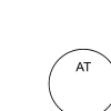 |
Measures and transmits analysis results remotely. |
| Computer Indicator | 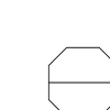 |
Displays digital information from measurement devices. |
| Flow Controller | 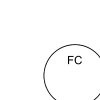 |
Regulates flow rate within the system. |
| Flow Element |  |
Detects flow in pipes or channels. |
| Flow Indicator |  |
Visually shows flow rate information. |
| Flow Recorder |  |
Records and logs flow rate data. |
| Flow Transmitter |  |
Converts flow data to electrical signals. |
| Indicator 1 | 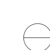 |
Displays first measurement parameter visually. |
| Indicator 2 | 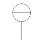 |
Displays second measurement parameter visually. |
| Indicator 3 |  |
Displays third measurement parameter visually. |
| Indicator 4 |  |
Displays fourth measurement parameter visually. |
| Indicator 5 |  |
Displays fifth measurement parameter visually. |
| Level Alarm | 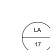 |
Signals when level exceeds preset limits. |
| Level Controller | 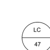 |
Regulates fluid levels within specified range. |
| Level Gauge | 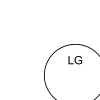 |
Provides visual indication of fluid levels. |
| Level Indicator | 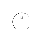 |
Displays real-time fluid level information. |
| Level Recorder | 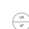 |
Logs fluid level data over time. |
| Level Transmitter | 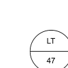 |
Converts fluid level readings to signals. |
| Pressure Controller | 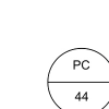 |
Maintains pressure within specified limits. |
| Pressure Indicating | 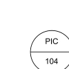 |
Displays current pressure value visually. |
| Pressure Recorder | 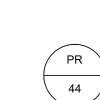 |
Logs and records pressure measurements over time. |
| Pressure Recording | 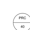 |
Captures and documents pressure changes continually. |
| Pressure Transmitter | 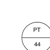 |
Sends pressure data as electrical signal. |
| Programmable Indicator | 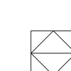 |
Customizable display for various process parameters. |
| Shared Indicator 1 | 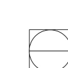 |
Displays shared process measurement visually. |
| Shared Indicator 2 | 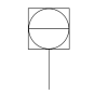 |
Displays additional shared process measurement. |
| Temp Controller | 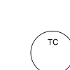 |
Maintains temperature within desired range. |
| Temp Indicator | 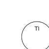 |
Displays temperature readings visually in real-time. |
| Temp Recorder | 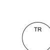 |
Logs and tracks temperature over time. |
| Temp Transmitter | 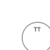 |
Converts temperature data to electrical signals. |
| Temperature Element | 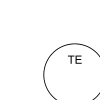 |
Detects temperature in process or equipment. |
| Transducer | 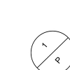 |
Converts physical measurement into electrical signal. |
P&ID Instrumentation Symbols and Their Identification
Each P&ID instrument symbol typically contains several key components to convey essential information:
1. Function Code: : The function code is an alphabetic identifier used in P&ID symbols for instrumentation to describe what process variable is being measured and the function performed by the instrument. These standardized letter combinations, based on ISA S5.1, make it easier for engineers, operators, and maintenance teams to quickly interpret instrument tags across process industries.
| First Letter (Measured Variable) | Second Letter (Instrument Function) |
|---|---|
| F — Flow | I — Indicator |
| T — Temperature | R — Recorder |
| P — Pressure | T — Transmitter |
| L — Level | C — Controller |
| A — Analyzer | E — Element |
For example, FT represents a Flow Transmitter, PI denotes a Pressure Indicator, and LIC refers to a Level Indicating Controller. Understanding these letter combinations enables engineers to accurately identify instrument functions, troubleshoot systems efficiently, and maintain consistency across engineering documentation.
2. Tag Number: It is a unique identification number assigned to each instrument. For example, FT-101 would represent a flow transmitter with the tag number 101.
3. Indicating and Recording Devices: Some symbols may include indicators or recorders that display the real-time status of the process variable or record data for analysis.
4. Connection Types: Lines between symbols indicate how devices are interconnected. These can represent pneumatic, electrical, or hydraulic connections, depending on the control system’s design.
How to Read P&ID Instrument Symbols?
Reading P&ID symbols for instrumentation discipline requires an understanding of the functional role of each device in the system.
Here are a few steps to help interpret P&ID diagrams effectively:
- Determine the Process Flow: It’s critical to comprehend how materials move through the system. Arrows are frequently used to show the direction of the flow, and the flow path will link different instrumentation symbols.
- Recognize the Purpose of Every Symbol: Every symbol stands for a certain purpose, such as safety, control, or measurement. You can interpret each symbol’s function in the system if you know what it stands for.
- Look for Control Loops: A lot of P&ID diagrams depict control loops, in which controllers use data from measuring devices to modify flow, pressure, or other process parameters.
- Take Note of Tag Numbers: Every instrument will have a distinct tag number that enables you to compare it with specifications or data sheets for further in-depth details.
Final Words
The design, operation, and purpose of instrumentation and control systems in industrial processes are all represented by P&ID instrumentation symbols. A thorough comprehension of these symbols guarantees adherence to industry standards, facilitates design and debugging, and encourages effective communication. Our instrumentation & control engineering services at Rishabh Pro Engineering include accurate and thorough P&ID designs that are customized to your project’s requirements. We provide solutions that are optimized for operational reliability, efficiency, and safety using a multidisciplinary approach. Our expertise makes it possible for you to use precise, standardized P&ID instrument symbols for smooth operations and reliable process control, whether you’re creating a new process or maintaining an old system.
Frequently Asked Questions On Instrumentation P&ID Symbols
Q: What standard governs instrumentation symbols in P&IDs?
A: The most widely recognized standard for P&ID instrumentation symbols is ISA-5.1 (Instrumentation Symbols and Identification), developed by the International Society of Automation (ISA). It defines standardized symbols, identification tags, and naming conventions for instrumentation used in process industries. Many engineering companies also align their P&IDs with ISO 10628 and client-specific drafting standards to ensure consistency across multidisciplinary engineering projects.
Q: What is the difference between a transmitter and a controller in a P&ID?
A: In a P&ID, a transmitter (T) measures a variable process such as pressure, temperature, flow, or level and sends the data to a control system. A controller (C) receives this information, compares it with the desired setpoint, and adjusts the process by sending commands to control elements like valves or actuators. While transmitters provide process measurements, controllers are responsible for maintaining process stability and achieving the required operating conditions.
Q: How are DCS and PLC instruments represented in a P&ID?
A: Distributed Control System (DCS) and Programmable Logic Controller (PLC) instruments are represented using standard instrument symbols combined with functional identification tags. Depending on the project’s drafting conventions, additional notations or symbol variations may indicate whether an instrument is connected to a DCS, PLC, or local control panel. These representations help engineering, automation, and operations teams understand the control architecture during design, commissioning, and maintenance.
Q: Can P&ID instrumentation symbols vary between projects?
A: Yes. Although most organizations follow standards such as ISA-5.1, symbol usage can vary based on client specifications, industry requirements, engineering consultants, and project-specific drafting guidelines. Before starting a project, engineering teams typically establish a standardized legend and symbol library to ensure consistency throughout the design documentation.
Q: How does a multidisciplinary engineering team use P&ID instrumentation symbols?
A: P&ID instrument symbols serve as a common engineering language across multiple disciplines, including process, piping, instrumentation, electrical, mechanical, and automation engineering. These symbols help teams coordinate equipment layouts, define control strategies, develop piping and cable routing, perform safety reviews, and support commissioning activities. A standardized P&ID reduces design errors, improves collaboration, and ensures efficient project execution throughout the engineering lifecycle.