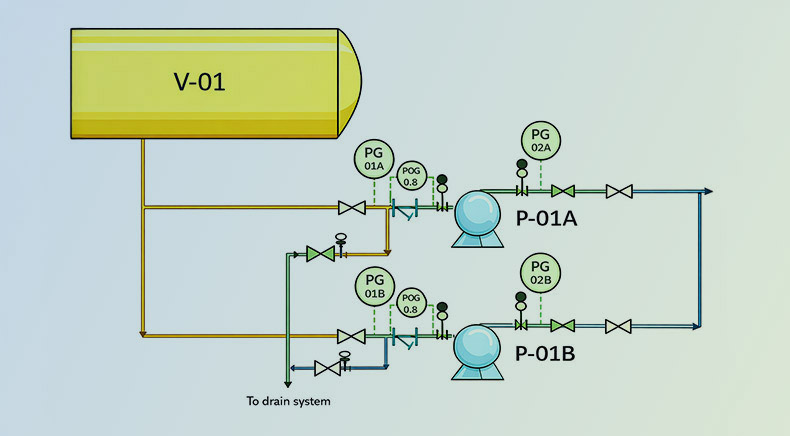
In the realm of process engineering, Piping and Instrumentation Diagrams (P&IDs) are crucial tools for visualizing and conveying the design, configuration, and operation of systems. P&ID pump symbols, specifically, are an essential part of these diagrams. They serve as visual shorthand, simplifying the complexity of fluid handling systems, pumps, and associated piping.
This blog takes a deep dive into P&ID pump symbols — what they are, how they are used, why they are important, how to read and interpret them along with guidelines and best practices for creation. For engineers, designers, and operators alike, understanding pump symbols is critical to both interpreting and developing process designs that are safe, functional, and compliant with industry standards.
What are P&ID Symbols For Pumps?
These symbols represent pumps in a process system. They help visually communicate the type of pump, its operating mode, and its functional attributes. These symbols help engineers, operators, and maintenance personnel easily identify and understand the pumping system’s design and operation. Each symbol is standardized and corresponds to a specific type of pump, ensuring clarity across designs and teams.
Types of P&ID Pump Symbols
| Pump Type | Symbol Shape Description | Typical Application |
|---|---|---|
| Centrifugal Pump | Usually shown as a circular symbol with an impeller or directional flow indication. | Water transfer, cooling systems, chemical processing, utility services. |
| Positive Displacement Pump | Circular or rectangular symbol with internal displacement markings indicating trapped-volume fluid movement. | High-pressure and constant-flow applications. |
| Gear Pump | Depicted with two intermeshing gears inside a circular or rectangular outline. | Lubrication systems, oil transfer, hydraulic services. |
| Diaphragm Pump | Symbol contains a diaphragm-shaped element separating the pumping chamber. | Corrosive, abrasive, or viscous fluid handling. |
| Peristaltic Pump | Circular symbol with curved rollers or tubing path representing squeezing action. | Chemical dosing, pharmaceutical, and food processing applications. |
| Screw Pump | Features a screw or helical element within the symbol. | High-viscosity fluids, crude oil transfer, multiphase flow applications. |
| Reciprocating Pump | Typically represented by a piston, plunger, or reciprocating motion indicator. | High-pressure injection systems, boiler feed, and hydraulic applications. |
| Vacuum Pump | Standard pump symbol combined with vacuum-service notation or suction indicator. | Vacuum generation, degassing systems, and process evacuation services. |
| Metering Pump | Often shown as a pump symbol with a dosing or controlled-flow indicator. | Precise chemical injection and additive dosing systems. |
| Lobe Pump | Contains two or more lobes within the symbol. | Hygienic applications in food, beverage, and pharmaceutical industries. |
Components of Pump P&ID Symbols
Listed below are the broad categories of pump symbols in P&IDs that define the pump’s function and usage details:
- Pump Type: Indicated by the specific symbol (centrifugal, diaphragm, gear, etc.).
- Flow Direction: Arrows show the direction in which the fluid flows.
- Control Features: Some symbols will indicate specific control features, such as variable speed or automatic shutdown capabilities.
- Drive Information: Some symbols include supplementary annotations or text to describe operational details, such as the motor, turbines type or drive configuration.
P&ID – Pump Symbols
They represent the different types of pumps used in process systems and help simplify complex fluid handling operations. Each symbol visually communicates the pump’s type, function, and orientation, ensuring consistency and clarity across engineering teams. From centrifugal, screw, and gear pumps to diaphragm, metering, and submerged pumps, every symbol follows standardized conventions like ISO or ANSI. These graphical notations also include details such as flow direction, motor drive, or control features. Accurate pump symbols make it easier for engineers, operators, and maintenance teams to interpret, design, and troubleshoot process systems effectively.
Now let’s explore the detailed representation of pumps within P&IDs that we consider;
| Type of Pump | Supportive Icon | Message |
|---|---|---|
| AODD Pump | 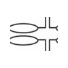 |
Air-operated double diaphragm pump symbol. |
| Cavity Pump | 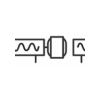 |
Positive displacement pump with cavity mechanism. |
| Centrifugal Pump 1 |  |
Basic centrifugal pump with standard impeller. |
| Centrifugal Pump 2 | 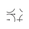 |
Single-stage centrifugal pump with inlets. |
| Centrifugal Pump 3 |  |
Multi-stage centrifugal pump with multiple impellers. |
| Centrifugal Pump 4 |  |
Horizontal centrifugal pump with horizontal flow. |
| Centrifugal Pump 5 |  |
Vertical centrifugal pump with vertical flow. |
| Dosing Pump | 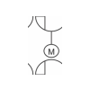 |
Precise flow control for chemical injection. |
| Hand Pump |  |
Manual pump operated by hand movement. |
| Gear Pump 1 | 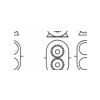 |
Positive displacement pump with gears. |
| Gear Pump 2 |  |
Rotary gear pump for consistent flow. |
| Horizontal Pump | 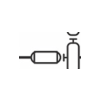 |
Pump with horizontal orientation for flow. |
| ISO Centrifugal Pump |  |
Centrifugal pump per ISO standards. |
| ISO Diaphragm Pump |  |
Diaphragm pump compliant with ISO standards. |
| ISO Gear Pump |  |
Gear pump meeting ISO specifications. |
| ISO Liquid Pump |  |
Liquid pump following ISO design standards. |
| ISO Positive Displacement Pump |  |
Positive displacement pump per ISO requirements. |
| ISO Progressing Cavity Pump |  |
Pump with ISO standard cavity mechanism. |
| ISO Progressing Pump 1 |  |
ISO-compliant progressing cavity pump system. |
| ISO Progressing Pump 2 |  |
Another ISO-compliant progressing pump configuration. |
| Liquid Ring Vacuum Pump | 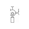 |
Vacuum pump with liquid ring mechanism. |
| Lobe Pump |  |
Positive displacement pump with rotating lobes. |
| ISO Screw Pump 1 |  |
ISO standard screw pump symbol. |
| ISO Screw Pump 2 |  |
Another version of ISO screw pump. |
| Metering Pump |  |
Precise liquid metering pump symbol. |
| Positive Displacement Pump 1 | 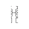 |
General symbol for positive displacement pump. |
| Positive Displacement Pump 2 |  |
Another variation of positive displacement pump. |
| Positive Displacement Pump 3 |  |
Different design for positive displacement pump. |
| Proportioning Pump 1 |  |
Pump symbol for proportional flow control. |
| Proportioning Pump 2 | 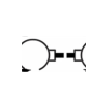 |
Another proportional flow control pump symbol. |
| Motor | 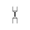 |
Motor symbol used to drive pump. |
| Reciprocating Pump 1 | 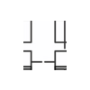 |
Pump using reciprocating motion to transfer fluids. |
| Reciprocating Pump 2 |  |
Another type of reciprocating pump system. |
| Peristaltic Pump |  |
Pump with peristaltic fluid transfer mechanism. |
| Screw Pump 1 |  |
Single screw pump for low-viscosity fluids. |
| Screw Pump 2 | 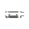 |
Another configuration of screw pump symbol. |
| Pump | 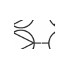 |
Generic symbol representing a pump. |
| Submerged Pump |  |
Pump submerged in the fluid for operation. |
| Submersible Pump |  |
Another submerged pump configuration for fluids. |
| Rotary Gear Pump | 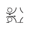 |
Rotary pump with interlocking gears mechanism. |
| Vane Pump 1 | 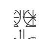 |
Pump with rotary vanes for fluid transfer. |
| Vane Pump 2 |  |
Another variation of vane pump system. |
| Rotary Pump | 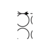 |
Positive displacement rotary pump symbol. |
| Vertical Bottom Suction Pump | 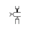 |
Vertical pump with bottom suction intake. |
| Vertical Canned Pump | 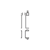 |
Vertical pump with canned motor setup. |
| Vertical Inline Centrifugal Pump | 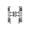 |
Vertical pump with inline centrifugal flow. |
| Vertical Pump | 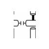 |
General vertical pump with fluid moving vertically. |
| Vertical Turbine Pump | 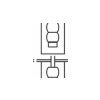 |
Turbine pump designed for vertical installation. |
| Sump Pump | 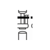 |
Pump for removing accumulated water or liquids. |
| Turbine Pump | 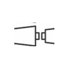 |
Pump with turbine mechanism for fluid movement. |
| Triplex Pump | 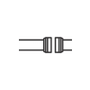 |
Triplex pump with three pistons or plungers. |
How to Read Pump Symbols?
Interpreting pump symbols correctly is essential for understanding process flow, equipment functionality, and system operation. Follow these steps when reviewing a P&ID:
Step 1: Identify the Pump Symbol
Locate the pump symbol on the drawing and determine its type. The shape and internal markings help distinguish whether it is a centrifugal, gear, diaphragm, screw, reciprocating, or another pump type.
Step 2: Check the Equipment Tag Number
Review the pump tag associated with the symbol, such as P-101, P-202A, or PU-301. The tag links the pump to equipment datasheets, specifications, and maintenance records.
Step 3: Determine the Flow Direction
Follow the arrows connected to the suction and discharge lines. These arrows indicate the direction in which fluid moves through the system.
Step 4: Review Pump Configuration
Examine any additional symbol details that indicate whether the pump is horizontal, vertical, multistage, submersible, or configured for a specific service.
Step 5: Identify the Driver Type
Look for connected motor, turbine, engine, or other driver symbols. These indicate how the pump receives power and operates within the process.
Step 6: Analyze Instrumentation and Controls
Review nearby instruments such as pressure gauges, flow transmitters, temperature sensors, and control valves. These components provide insight into pump monitoring and control requirements.
Step 7: Check Safety and Protection Features
Identify associated equipment such as relief valves, bypass lines, strainers, check valves, and alarms that protect the pump and process system.
Step 8: Verify Applicable Standards
Refer to the project legend and applicable standards such as ISO 10628 or ANSI/ISA conventions to ensure accurate interpretation of the symbol and associated notations.
Guidelines to Prepare P&ID for Pumps
Creating a Pump P&ID is a critical step in process engineering projects. This helps ensure clarity in system operation, maintenance, and safety. Listed below are commonly used guidelines that outline the best practices for preparing effective Pump P&IDs:
Define Pump Type and Service
- Identify the pump type: centrifugal, positive displacement, gear, diaphragm, or peristaltic.
- Specify service conditions: process fluid, pressure, temperature, and flow rate.
Include Complete Pump Data
- Pump ID, tag number, and manufacturer details.
- Design flow rate, suction and discharge pressure, NPSH (Net Positive Suction Head), and efficiency.
- Power source and motor rating.
Represent Pump Orientation and Configuration
- Include pump arrangement: horizontal, vertical, inline, or multistage.
- Show suction and discharge connections with proper orientation.
- Indicate mechanical seals or packing arrangement.
Integrate Control and Safety Instruments
- Include flow, pressure, and temperature transmitters near suction and discharge.
- Show control valves, isolation valves, and bypass lines.
- Add alarms, interlocks, and safety relief devices.
Show Suction and Discharge Piping
- Include line sizes, material specifications, and insulation if required.
- Represent suction strainers, filters, or separators upstream of the pump.
- Show discharge check valves and pressure relief valves.
Depict Ancillary Equipment
- Include lube oil systems, cooling water lines, and seal flush lines if applicable.
- Indicate vents, drains, and instrumentation taps.
Follow Standard Symbols and Conventions
- Use standard P&ID symbols (ISA, ISO, or company standards) consistently.
- Maintain clear line identification, direction of flow, and tag numbers.
- Ensure P&ID clarity for operators, engineers, and maintenance teams.
Review and Validation
- Cross-check P&ID with process datasheets, specifications, and equipment layouts.
- Validate for safety compliance, operational logic, and maintainability.
- Conduct peer review to minimize errors and omissions.
Documentation
- Maintain version control and revision history.
- Include a legend or key for easy understanding of symbols and notations.
Best Practices When Reading or Creating Pump Symbols in P&IDs
- Stick to Standard Conventions: Use ISO, ANSI/ISA, or client-specific legend sheets to ensure symbols match accepted standards.
- Consistency is Key: Across all P&IDs in a project, ensure that the same symbol style is used for similar equipment.
- Avoid Overcomplication: A symbol doesn’t need to show every mechanical detail—only those necessary for understanding process operation and control.
- Use Cross – Referencing Efficiently: Use tag numbers and line identifiers to cross reference vessels with other drawings, datasheets, and specifications.
- Consult the Legend Sheet: Always refer to the project specific symbol legend to understand customized symbols or notations.
The Role of Multidisciplinary Engineering in P&ID Development
Developing and interpreting pump symbols is not only the domain of process engineers. It requires input from multiple disciplines:
- Mechanical Engineering: Ensures pump design that matches process needs.
- Instrumentation & Control: Ensures mapping of transmitters, sensors, and control elements.
- Piping Engineering: Manages connectivity, nozzle locations, and routing.
- Safety Engineering: Ensure emergency and relief measures are appropriately represented.
A multidisciplinary engineering company like Rishabh Pro Engineering integrates all these perspectives to deliver P&IDs that are technically sound, compliant, and project ready. Read this blog to explore different piping and instrumentation diagram symbols, how to read P&IDs and how to craft them.
Why are P&ID Pump Symbols Important?
P&ID pump symbols provide a unified visual language that helps engineers, designers, and maintenance teams understand the mechanical systems without ambiguity. By reading a P&ID with the correct symbols, teams can:
- Easily identify pump types and their application
- Understand flow and pressure requirements
- Ensure efficient maintenance and troubleshooting
- Maintain consistent communication across different stakeholders
Final Words
P&ID symbols for pumps are vital for accurately representing complex pump systems and their integration within process plants. They enable clarity and consistency in system design, operation, and maintenance. Whether creating new layouts or troubleshooting existing ones, standardized pump symbols ensure smooth collaboration across teams and projects. At Rishabh Pro Engineering, through our equipment engineering services, we deliver comprehensive P&ID designs with standardized pump symbols tailored for diverse industrial applications. Backed by a multidisciplinary approach, we ensure that every design meets global codes, safety requirements, and operational efficiency standards.
Frequently Asked Questions On Pump P&ID Symbols
Q: What is a P&ID pump symbol and why does it matter?
A: A P&ID pump symbol is a standardized graphical representation of a pump within a Piping and Instrumentation Diagram. It communicates the pump’s type, function, orientation, and operational role within the process system. Standardized symbols improve design accuracy, reduce interpretation errors, and support efficient operation and maintenance.
Q: Which standards govern pump P&ID symbols?
A: Pump symbols in P&IDs are primarily governed by standards such as ISO 10628, ISO 14617, and ANSI/ISA-5.1. Many organizations also apply client-specific or company engineering standards. These standards ensure consistency, clarity, and uniform interpretation across multidisciplinary engineering teams.
Q: How are pumps tagged and numbered in a P&ID?
A: Pumps are assigned to unique equipment identification tags such as P-101, P-102A, or PU-301. The tag typically consists of a functional equipment code, followed by a unique numerical identifier. These tags correspond to equipment datasheets, specifications, maintenance records, and asset management systems.
Q: What is the difference between a centrifugal pump symbol and a positive displacement pump symbol in a P&ID?
A: A centrifugal pump symbol typically represents an impeller-driven pump used for continuous flow applications and is often shown with a circular impeller-style representation. A positive displacement pump symbol includes design elements indicating fluid displacement through gears, pistons, screws, lobes, or diaphragms. While centrifugal pumps are generally flow-dependent on system conditions, positive displacement pumps deliver a nearly constant flow rate regardless of pressure variations.
Q: What is the difference between ISO and ANSI/ISA pump symbols?
A: Both ISO and ANSI/ISA standards aim to provide standardized equipment representations, but they may differ slightly in graphical style, notation conventions, and symbol details. ISO standards are widely used in international projects, while ANSI/ISA standards are commonly adopted in North America. Project legend sheets should always be referenced to confirm the symbol conventions being used.