The client was in the process of standardizing & customizing 3D models, fabrication drawings & another project database of operation & manufacturing data designs to meet the growing demands for advancement in the product line. They were looking for an established engineering support services provider to take up this work and ensure a higher level of data security and highly detailed designs, helping them create a High-Value Engineering Center (HVEC).
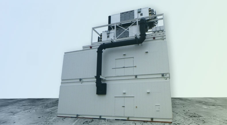
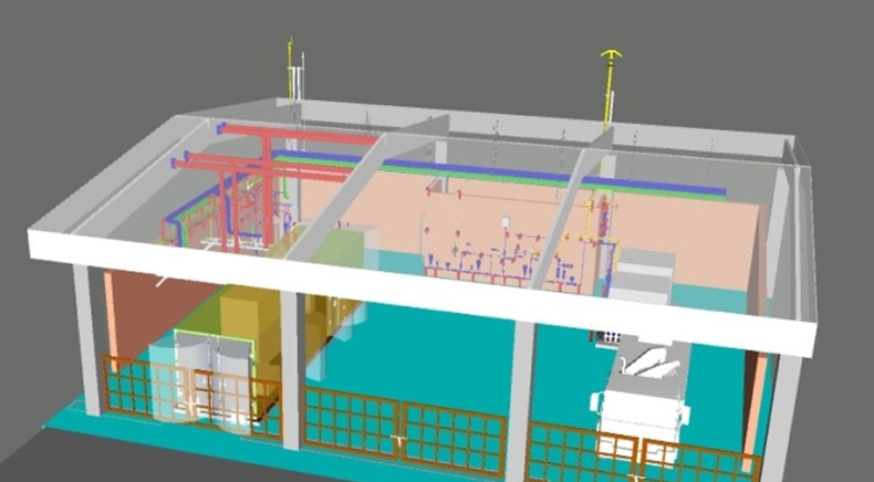
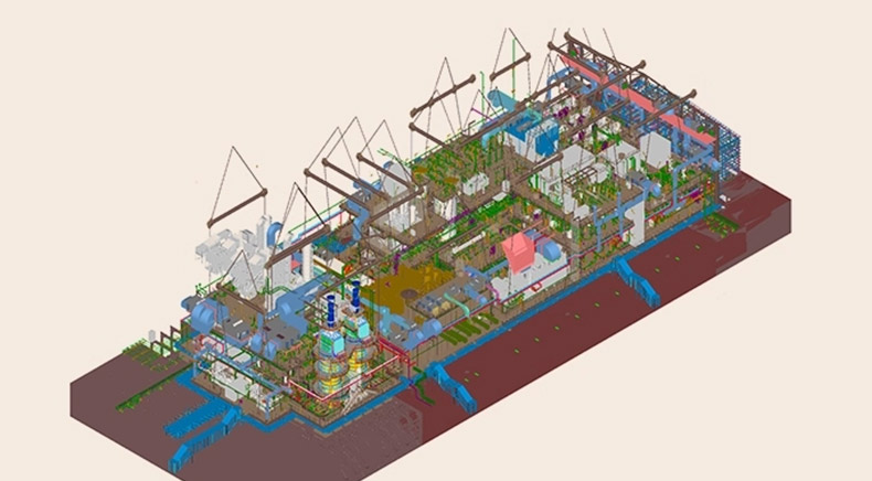
Appointed as their 3D CAD modeling services partner, our job was to create a 3D Model of the Power Generator Enclosure, extract fabrication drawings, and more, including complete detailed fabrication drawings packages. As part of this, our primary challenge was to create engineering drawings based on the initial GA. It included an enclosure that involved HVAC ducting routing inside the completed enclosure. The air cooling requirements, heat exchanger sizing, louver sizes & filter static pressure were to be considered.
Project Deliverables
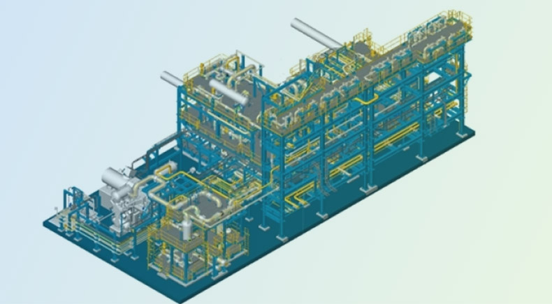
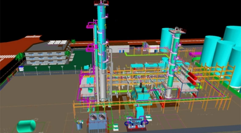
Complete 3D modeling of the enclosure using advanced tools like SOLIDWORKS while incorporating HVAC ducting routing, air cooling requirements, heat exchanger sizing, louver sizes, and filter static pressure.
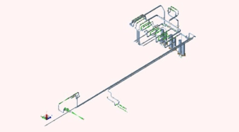
Extraction of fabrication drawings from the 3D model, including all dimensions, tolerances, and material specifications for manufacturing.
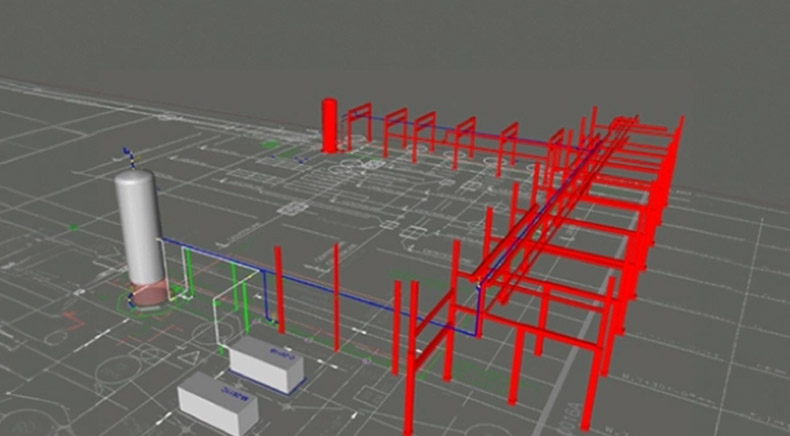
Comprehensive details of equipment foundations while ensuring accurate placement and structural integrity during installation.
Line diagrams and layouts for all electrical control/AMF panels, including switchgear ratings, disposition, cable feeder sizes, and layout plans.
Detailed schematics of control components.
Sequence of operations to explain control circuit functionality. Project Database Standardization
Organized and customized database for operations and manufacturing data designs while ensuring higher data security and consistency across the product line.
Backed by advanced modeling tools and sophisticated software like SOLIDWORKS, we were able to create master 3D drawings.