Unexpected equipment failures can disrupt operations, compromise safety, and lead to significant financial losses due to unplanned downtime, costly repairs, and production delays. While traditional failure investigations rely on visual inspections, material testing, non-destructive testing (NDT), and metallurgical analysis to identify where and how a component failed, they often fall short of explaining why the failure occurred under actual operating conditions. Factors such as stress concentrations, thermal expansion, cyclic loading, vibration, and complex load interactions are difficult to evaluate through physical inspection alone.
This is where finite element analysis (FEA) plays a critical role. By simulating real-world operating conditions in a virtual environment, this failure analysis enables engineers to visualize structural behavior, identify root causes, and validate corrective actions before implementing design changes. Widely used across industries including oil and gas, chemical processing, power generation, and heavy manufacturing, FEA helps improve equipment reliability, prevent recurring failures, extend asset life, and reduce overall lifecycle costs.
In this article, we explore how Finite Element Analysis supports failure analysis, the types of engineering failures it can investigate, and the structured approach engineers follow to uncover root causes and develop reliable, long-term solutions.
What Is Failure Analysis in Engineering?
Failure analysis is the process of understanding why an engineering component or system stopped performing as intended. Rather than simply repairing visible damage, engineers investigate the underlying factors that contributed to the failure, such as excessive stress, material degradation, fatigue, thermal expansion, corrosion, vibration, manufacturing defects, or improper operating conditions. The objective is not only to identify what went wrong but also to determine the root cause, so the problem does not recur.
A comprehensive finite element modeling in failure analysis combines visual inspections, NDT, material evaluation, and engineering simulations such as FEA to understand how a component behaved under real-world operating conditions. By uncovering the true cause of failure, organizations can improve equipment reliability, enhance safety, optimize future designs, reduce maintenance costs, and minimize unplanned downtime across critical industrial assets.
Why Traditional Failure Investigations Are Not Enough
When critical industrial equipment fails, the immediate focus is often on restoring operations through visual inspections, NDT, metallurgical examinations, and material analysis. While these techniques effectively identify visible damage such as cracks, corrosion, wear, or material defects, they primarily reveal what failed rather than why it failed under actual operating conditions.
Components such as pressure vessel nozzles, pipelines, rotating equipment, and structural supports are exposed to complex combinations of mechanical loads, thermal expansion, fluctuating pressures, vibration, and cyclic stresses throughout their service life. These interacting forces can create hidden stress concentrations or dynamic effects that remain undetected during conventional inspections. Simulation-driven engineering addresses this gap by recreating real operating conditions through FEA, enabling engineers to evaluate structural behavior, visualize stress distribution, predict deformation, and identify the true root cause of failure. This allows organizations to validate corrective actions, prevent recurring failures, and improve long-term equipment reliability.
Understanding the Role of FEA & FEM in Failure Analysis
The terms FEA and finite element method (FEM) are often used interchangeably, but they refer to different aspects of the same engineering process. FEM is the mathematical and numerical technique used to divide a complex structure into smaller, manageable elements for analysis. While FEA, on the other hand, is the practical application of this method using engineering simulation software to evaluate how components behave under real-world operating conditions. Simply put, FEM is the methodology, while FEA is the engineering analysis performed using that methodology.
In failure analysis, FEA acts as a virtual testing environment where engineers can recreate failed components and investigate how they responded to actual service conditions before the failure occurred. Instead of relying solely on physical evidence, engineers can simulate the operating environment to understand the sequence of events that led to the failure.
The process begins by developing a three-dimensional model of the failed component using CAD data, engineering drawings, or reverse engineering techniques. Material properties such as elasticity, yield strength, thermal conductivity, and fatigue characteristics are assigned to accurately represent the component’s behavior. Engineers then apply realistic boundary conditions, including operating loads, internal pressure, temperature variations, vibration, support constraints, or impact forces.
Using the finite element method, the model is discretized into thousands or even millions of interconnected elements. The simulation then calculates stress, strain, displacement, deformation, and safety factors across the entire component, enabling engineers to identify localized stress concentrations, excessive deformation, or fatigue-prone regions that may have triggered the failure.
Unlike conventional inspection techniques, FEA allows engineers to evaluate multiple failure scenarios without physically modifying the equipment. Alternative materials, design modifications, support arrangements, loading conditions, or reinforcement strategies can be assessed virtually, helping validate engineering assumptions and identify the most probable root cause before implementing corrective actions.
Today, FEA has become an indispensable tool for forensic engineering, equipment reliability studies, product development, fitness-for-service assessments, and life extension programs. By combining the mathematical foundation of FEM with advanced simulation capabilities, engineers can make more informed decisions, reduce engineering uncertainty, and develop solutions that improve safety, reliability, and long-term asset performance.
Visual/NDT Inspection vs. FEA-Based Failure Analysis
Traditional inspection methods such as visual examination, NDT, and metallurgical analysis remain essential for evaluating the condition of industrial equipment after a failure. They provide valuable evidence about cracks, corrosion, material degradation, and manufacturing defects. However, these methods primarily explain what has failed based on physical observations. FEA complements these inspections by recreating real operating conditions in a virtual environment to determine why the failure occurred. By evaluating stress distribution, thermal effects, vibration, and structural behavior under actual service loads, FEA helps engineers validate failure mechanisms, identify hidden design weaknesses, and develop engineering solutions that prevent recurrence. Rather than replacing conventional inspection techniques, FEA works alongside them to deliver a more complete and reliable failure investigation.
| Parameter | Visual / NDT Inspection | FEA-Based Failure Analysis |
| Primary Objective | Detect visible defects, cracks, corrosion, or material degradation | Identify the engineering mechanism responsible for the failure |
| Answers | What failed? | Why did it fail? |
| Approach | Physical inspection and testing | Virtual simulation under real operating conditions |
| Evaluates | Surface defects, weld quality, material condition | Stress, strain, deformation, thermal effects, fatigue, vibration |
| Hidden Failure Mechanisms | Limited visibility | Identifies stress concentration, load paths, and structural weaknesses |
| Considers Operating Loads | No | Yes—pressure, temperature, vibration, cyclic loading, and external forces |
| Root Cause Identification | May require assumptions | Validated using engineering simulation and calculations |
| Corrective Action | Repair or replace damaged components | Optimize design, supports, materials, geometry, or operating conditions |
| Best Use Case | Initial condition assessment and defect detection | Root cause investigation, design validation, and recurrence prevention |
| Business Outcome | Restores equipment to service | Improves long-term reliability, safety, and asset performance |
Common Engineering Failures That Can Be Investigated Using FEA
Equipment failures rarely occur due to a single isolated factor. Most failures result from a combination of loading conditions, material behavior, environmental influences, and design limitations. FEA enables engineers to simulate these conditions simultaneously, making it easier to identify the dominant failure mechanism and recommend effective corrective actions.
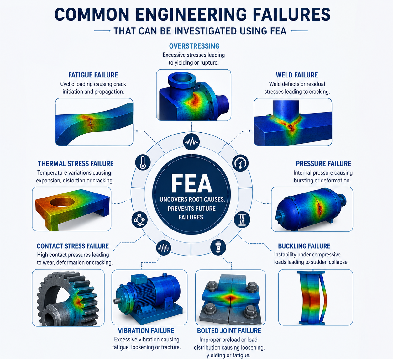
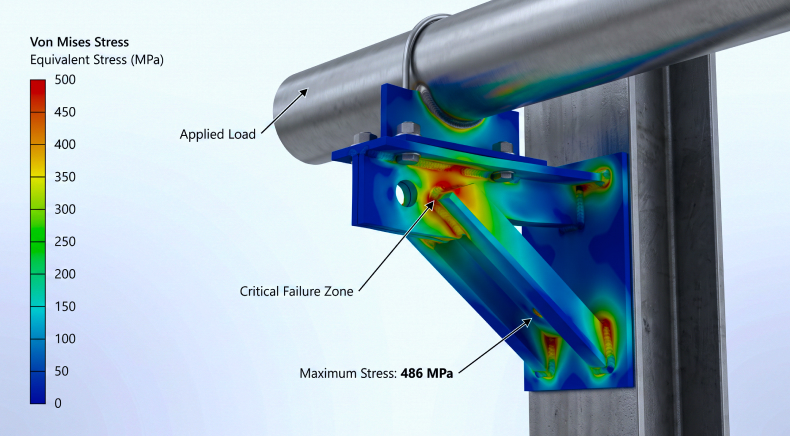
- Stress-Induced Failure: Localized stress concentrations are among the most common causes of structural failure. Features such as sharp corners, geometric discontinuities, holes, keyways, weld joints, and sudden changes in cross-section often create regions where stresses become significantly higher than the average applied load. Using FEA, engineers can visualize these stress concentrations and determine whether localized yielding or fracture initiation is likely to occur. The analysis also helps optimize component geometry by introducing smoother load paths, improved fillet radii, or reinforcement features that reduce peak stress levels and improve structural reliability.
- Fatigue Failure: Many industrial components operate under repeated loading rather than a single static load. Pumps, compressors, rotating shafts, support structures, and pressure systems experience millions of stress cycles throughout their service life. Even when individual stress levels remain below the material’s yield strength, repeated cyclic loading can initiate microscopic cracks that gradually propagate until catastrophic failure occurs. Fatigue analysis within FEA enables engineers to estimate fatigue life, identify crack initiation zones, evaluate stress amplitudes, and compare alternative design modifications. This capability is particularly valuable for extending equipment life and planning predictive maintenance strategies before fatigue-related failures occur.
- Thermal Failure: Temperature variations significantly influence the structural behavior of industrial equipment. Differential thermal expansion between connected components, repeated heating and cooling cycles, and localized temperature gradients may introduce stresses that exceed those caused by mechanical loading alone. FEA allows engineers to perform coupled thermal-structural analyses, predicting how elevated temperatures affect stress distribution, deformation, and material performance. This information supports the design of pressure vessels, heat exchangers, furnace components, piping systems, and high-temperature process equipment where thermal effects play a critical role.
- Pressure-Induced Failure: Pressure-containing equipment such as storage tanks, reactors, separators, boilers, and pipelines must safely withstand both internal and external pressures throughout their operating life. Localized overstressing near nozzles, openings, support connections, or welded joints can eventually result in leakage, plastic deformation, or structural failure. Pressure simulations performed through FEA help engineers verify stress distribution across pressure boundaries, assess reinforcement requirements, evaluate nozzle loads, and ensure compliance with applicable design codes and industry standards.
- Buckling and Stability Failure: Not all structural failures occur because material strength is exceeded. Slender columns, thin-walled vessels, storage tanks, and structural members may fail due to instability long before reaching their theoretical yield strength. Buckling analysis evaluates the critical load at which a component loses stability and experiences sudden deformation. This assessment is particularly important for support structures, offshore modules, towers, and lightweight industrial equipment where geometric instability can govern design performance.
- Vibration and Dynamic Failure: Industrial machinery continuously experiences dynamic forces generated by rotating equipment, fluid flow, reciprocating motion, and operational disturbances. If the operating frequency approaches the natural frequency of a structure, resonance may occur, leading to excessive vibration, accelerated fatigue, loosening of connections, and premature failure. Dynamic FEA enables engineers to perform modal, harmonic, and transient analyses to identify resonance conditions, evaluate vibration amplitudes, and recommend structural modifications that improve equipment reliability and operational stability.
- Contact and Assembly Failure: Many industrial components rely on precise contact interactions between mating surfaces to ensure safe and reliable operation. Bearings, couplings, press-fit assemblies, seals, valve seats, and sliding interfaces transfer loads through localized contact regions, where uneven pressure distribution or excessive deformation can accelerate wear, surface damage, fretting, or leakage. Conventional inspection methods often identify the resulting damage but cannot fully explain how contact forces contributed to the failure. Using FEA, engineers can simulate contact behavior under realistic operating conditions by evaluating friction, surface interaction, load transfer, and deformation between assembled components. The analysis helps visualize contact pressure distribution, identify localized stress concentrations, optimize component fit, and improve assembly tolerances. By validating contact performance before manufacturing or during failure investigations, organizations can reduce wear-related failures, improve sealing performance, and enhance the durability and reliability of critical mechanical assemblies.
- Bolted Joint and Flange Failure: Bolted joints and flange connections are critical to maintaining the structural integrity and leak-tight performance of industrial equipment such as pressure vessels, heat exchangers, piping systems, pumps, and compressors. Failures can occur due to insufficient bolt preload, uneven gasket compression, thermal expansion, cyclic loading, vibration, or excessive external piping forces, leading to bolt fatigue, flange distortion, gasket failure, or leakage. Finite Element Analysis enables engineers to simulate bolt pretension, contact pressure, gasket behavior, and operating loads to evaluate joint performance under actual service conditions. By analyzing load distribution across bolts and flange faces, engineers can identify overstressed regions, optimize bolt patterns and tightening sequences, verify gasket compression, and recommend design improvements that ensure reliable sealing. This simulation-driven approach helps prevent recurring joint failures, minimizes maintenance requirements, and improves the long-term safety and operational reliability of pressure-containing systems.
The FEA-Based Failure Analysis Process: A Systematic Engineering Approach
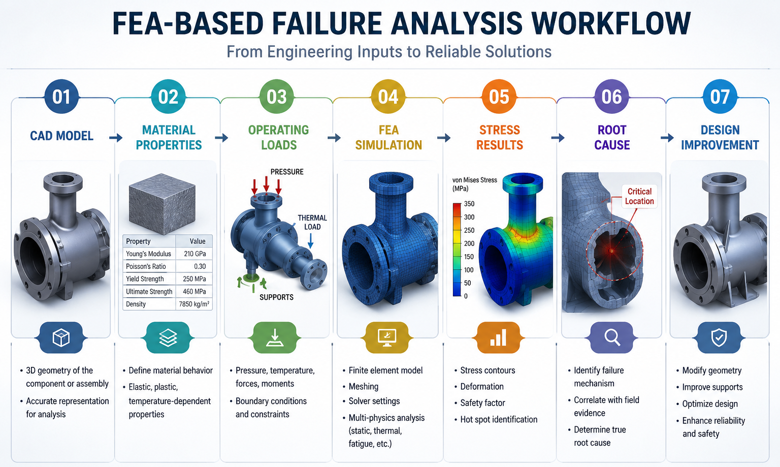
Failure analysis is most effective when it follows a structured methodology rather than relying on assumptions or isolated observations. Finite element analysis provides engineers with a repeatable process to evaluate failed components, validate engineering hypotheses, and develop corrective actions based on simulation results. The typical workflow includes the following stages:
Step 1: Failure Data Collection and Preliminary Investigation
Every successful failure analysis begins with gathering comprehensive information about the failed component and its operating environment. Engineers review equipment history, maintenance records, operating parameters, inspection reports, and failure photographs to establish the sequence of events leading to the incident. Additional inputs such as material certificates, process conditions, pressure and temperature records, and loading history help create a realistic representation of the component’s service conditions. This preliminary assessment narrows down potential failure mechanisms before simulation begins.
Step 2: Development of the Digital Model
The failed component is recreated using CAD models, engineering drawings, or reverse engineering techniques if original design data is unavailable. Simplifications may be introduced where appropriate without compromising the accuracy of the analysis. The model incorporates critical geometric features such as weld joints, openings, fillets, stiffeners, nozzles, and support arrangements, as these often influence stress distribution and structural behavior.
Step 3: Material Characterization and Boundary Conditions
The reliability of any simulation depends on accurately representing real-world operating conditions. Engineers assign material properties based on applicable standards or material test data, including elastic modulus, Poisson’s ratio, yield strength, thermal properties, and fatigue characteristics. Boundary conditions such as fixed supports, pressure loads, thermal gradients, vibration, external forces, and contact interactions are then applied to replicate actual service conditions as closely as possible.
Step 4: Simulation and Structural Analysis
Depending on the suspected failure mechanism, engineers perform one or more simulation studies, including:
- Static structural analysis for evaluating stress and deformation
- Thermal analysis to assess temperature-induced effects
- Fatigue analysis for cyclic loading conditions
- Modal and harmonic analysis to investigate vibration-related failures
- Buckling analysis for stability assessment
- Nonlinear analysis where material or geometric nonlinearity influences structural behavior
The resulting stress contours, deformation plots, strain distribution, and safety factors provide valuable insight into how the component behaves under operational loading.
Step 5: Root Cause Identification
Simulation results are compared with actual failure observations to determine whether the predicted stress concentrations, deformation patterns, or crack initiation locations align with physical evidence. Rather than identifying only the point of failure, engineers investigate the underlying mechanism responsible for initiating the damage. This distinction is critical because replacing a failed component without addressing the root cause often results in recurring failures.
Step 6: Engineering Recommendations and Design Optimization
The final stage focuses on implementing corrective actions that eliminate the identified failure mechanism. Depending on the findings, recommendations may include modifying component geometry, increasing section thickness, redesigning support arrangements, improving weld configurations, selecting alternative materials, or changing operating conditions. Because these improvements are validated through simulation before implementation, organizations can reduce engineering uncertainty while minimizing expensive trial-and-error modifications.
Industrial Applications of FEA in Failure Analysis
Finite Element Analysis has become an indispensable investigation tool across industries where equipment reliability, personnel safety, and uninterrupted operations are critical.
- Pressure Vessels and Storage Tanks: Localized cracking around nozzles, excessive shell deformation, or support failures often results from complex combinations of internal pressure, thermal expansion, and external piping loads. FEA helps engineers evaluate these interacting forces and identify design improvements that restore structural integrity while complying with applicable design codes.
- Piping Systems: Industrial piping networks experience pressure fluctuations, thermal expansion, dead weight, and vibration throughout their operational life. Simulation enables engineers to identify overstressed sections, optimize support spacing, assess nozzle loads, and investigate recurring piping failures without extensive physical testing.
- Rotating Equipment: Pump casings, compressor frames, motor bases, and turbines frequently encounter dynamic loading conditions that are difficult to evaluate using conventional inspection methods. Modal and harmonic analyses help identify resonance, excessive vibration, and fatigue-prone regions that may lead to premature equipment failure.
- Structural Steel and Support Systems: Industrial platforms, equipment foundations, pipe racks, lifting structures, and modular skids must withstand a combination of static, wind, seismic, and operational loads. FEA supports structural failure investigations by evaluating stress distribution, deformation, buckling behavior, and load paths under various operating scenarios.
- Heavy Industrial Equipment: Construction equipment, mining machinery, material handling systems, and fabricated assemblies are exposed to repeated impact loading and cyclic stresses throughout their service life. FEA helps identify fatigue-sensitive regions and optimize structural design for improved durability and longer service life.
Benefits of Using FEA for Failure Analysis
Organizations increasingly rely on simulation-based failure investigations because they provide engineering insights that extend beyond traditional inspection techniques.
- Faster Root Cause Identification: Instead of relying solely on physical evidence, engineers can recreate operating conditions virtually and evaluate multiple failure scenarios, significantly reducing the time required to identify the actual cause of failure.
- Reduced Equipment Downtime: Accurate diagnosis enables maintenance teams to implement targeted corrective actions rather than repeated repairs that fail to address the underlying problem. This reduces production interruptions and improves overall plant availability.
- Improved Design Reliability: Simulation highlights design weaknesses before equipment are returned to service. Engineering modifications can therefore be validated digitally, reducing the likelihood of repeat failures and increasing long-term asset reliability.
- Lower Maintenance and Lifecycle Costs: By preventing recurring failures and extending equipment life, organizations can reduce maintenance frequency, minimize spare part consumption, and optimize long-term operational expenditure.
- Enhanced Safety and Regulatory Compliance: FEA enables engineers to evaluate structural integrity under extreme operating conditions, helping organizations identify potential failure risks before they compromise personnel safety or environmental compliance.
- Data-Driven Engineering Decisions: Simulation provides quantitative engineering evidence that supports design improvements, retrofit decisions, warranty investigations, forensic engineering studies, and capital investment planning.
Best Practices for Effective FEA-Based Failure Analysis
The accuracy of a failure analysis study depends not only on the simulation software but also on the quality of engineering inputs and interpretation. To obtain meaningful results, engineers should follow several best practices.
- Use accurate material properties that reflect actual operating conditions rather than generic database values.
- Apply realistic boundary conditions and loading scenarios based on field measurements and operational data.
- Develop an appropriate mesh that balances computational efficiency with solution accuracy, particularly around stress concentration zones.
- Validate simulation results against inspection findings, material testing, and historical operating data whenever possible.
- Consider multiple failure mechanisms instead of assuming a single cause.
- Combine engineering judgment with simulation results to ensure conclusions remain practical and technically defensible.
It is equally important to recognize that FEA is not intended to replace conventional inspection techniques. Instead, it complements metallurgical analysis, non-destructive testing, and field investigations by providing deeper insight into how and why failures develop under operational conditions.
How Rishabh Pro Engineering Supports FEA-Driven Failure Analysis
Equipment failures often involve multiple interacting factors, including mechanical loading, thermal expansion, pressure fluctuations, vibration, fatigue, and structural constraints. Identifying the true root cause requires more than simulation software, it demands multidisciplinary engineering expertise and a thorough understanding of real-world operating conditions.
At Rishabh Pro Engineering, our finite element analysis consulting services help industrial organizations investigate equipment failures, validate engineering designs, and improve long-term asset reliability. Our engineers perform linear and nonlinear structural simulations, thermal-structural analysis, contact analysis, fatigue assessment, buckling evaluation, vibration studies, and code-compliant engineering assessments for static and rotating equipment.
Working alongside our expertise in pipe stress analysis and structural analysis, we provide an integrated engineering approach for pressure vessels, piping systems, structural steel, skids, process equipment, and heavy industrial machinery. By combining simulation with practical engineering knowledge, we help clients identify failure mechanisms, optimize designs, reduce operational risks, and enhance equipment performance across the entire asset lifecycle.
Whether you’re investigating an unexpected failure, validating a design modification, or improving the reliability of critical industrial assets, our simulation-driven engineering approach delivers actionable insights that support safer, more efficient, and more dependable operations.
FEA in Action: Real Engineering Failure Analysis Case Studies
Industrial failures often result from multiple interacting factors rather than a single design flaw. The following examples illustrate how Finite Element Analysis helps engineers move beyond visible damage to identify the underlying failure mechanism and recommend effective corrective actions.
Case 1: Finite Element Analysis of Critical Equipment Nozzles
A North American EPC company required engineering validation of process equipment nozzles connected to critical assets, including knockout drums, absorber overhead drums, absorber separators, and stripper towers. Conventional piping stress analysis indicated that several nozzle connections were experiencing significant loading; however, it was unclear whether these loads could compromise equipment integrity or result in premature failures during plant operation.
Rishabh Pro Engineering performed piping stress analysis using CAESAR II to evaluate sustained, thermal, and operating loads acting on the connected piping systems. The calculated nozzle loads were then transferred to NozzlePRO for detailed finite element analysis (FEA), enabling engineers to assess localized stress distribution around each equipment nozzle in accordance with ASME B31.3 and ASME Section VIII Division 2 requirements.
The simulation identified nozzle locations experiencing elevated localized stresses due to the combined effects of piping flexibility, thermal expansion, and external loading. Based on the FEA results, engineering recommendations were developed to optimize piping layouts and loading conditions, ensuring nozzle stresses remained within allowable design limits before fabrication and commissioning.
Engineering Insight: By combining piping stress analysis with finite element analysis of critical equipment nozzles, our engineering team identified localized overstressing at nozzle connections, enabling design optimization that minimized fatigue risks, prevented leakage, and improved long-term equipment reliability.
Case 2: Simulation-Driven Structural Validation of a Fired Heater Module
A UK-based engineering company required detailed engineering for a fired heater module designed for a seawater treatment plant in Alaska. Since the heater module would be fabricated offsite, transported across the Atlantic Ocean on a barge, and installed within a waste heat recovery facility, the structural integrity of the equipment needed to be validated under operational and transportation loading conditions.
Rishabh Pro Engineering developed a comprehensive 3D model using CADWorx and Tekla, followed by piping stress analysis using CAESAR II and structural analysis using STAAD.Pro Connect Edition. The integrated engineering study evaluated piping loads, structural response, lifting conditions, transportation loads, and foundation interactions to identify potential stress concentrations and design vulnerabilities before fabrication.
The engineering analysis enabled the team to recommend structural refinements and piping modifications that improved load distribution across the fired heater assembly while ensuring compliance with project specifications. By validating the design during the engineering stage, potential structural issues that could have emerged during transportation or plant operation were mitigated before construction commenced.
Engineering Insight: Through simulation-driven structural validation of a fired heater module, engineers evaluated structural performance under transportation and operational loading conditions, enabling design optimization that minimized excessive stresses, improved structural integrity, and reduced the likelihood of costly field modifications.
Common Mistakes That Lead to Incorrect FEA Failure Analysis
Finite Element Analysis is only as reliable as the engineering assumptions used to develop the model. Even advanced simulation software cannot compensate for unrealistic inputs or incorrect interpretation of results. Avoiding these common mistakes is essential for producing meaningful failure investigations.
- Using Simplified Boundary Conditions: Applying unrealistic support conditions or ignoring operational constraints can significantly alter stress distribution. Boundary conditions should accurately represent how the component behaves in service.
- Ignoring Thermal Effects: Many industrial failures occur because thermal expansion and temperature gradients interact with mechanical loading. Excluding thermal loads from the analysis may underestimate actual operating stresses.
- Poor Mesh Quality Around Critical Features: Stress concentrations typically occur near welds, fillets, holes, nozzles, and geometric discontinuities. An overly coarse mesh in these regions can produce misleading stress results and obscure the true failure mechanism.
- Assuming Ideal Material Properties: Actual material behavior may differ due to manufacturing processes, heat treatment, corrosion, or prolonged service exposure. Whenever possible, simulations should incorporate verified material data or laboratory test results.
- Overlooking Dynamic Loading: Static analysis alone cannot explain failures caused by vibration, impact loading, rotating equipment, or fluctuating process conditions. Dynamic simulations are often necessary to capture the complete operating environment.
- Treating Simulation as a Standalone Solution: FEA should complement not replace engineering inspections, non-destructive testing, metallurgical analysis, and operational data. Combining simulation with field evidence produces the most reliable conclusions.
Concluding Thoughts
Equipment failures rarely occur without warning. More often, they result from the gradual accumulation of stress, cyclic loading, thermal effects, vibration, or design limitations that remain unnoticed until a component reaches its failure threshold. While traditional inspection methods help identify the physical evidence of damage, they may not fully explain the engineering conditions that caused the failure.
Finite element analysis bridges this gap by enabling engineers to recreate real operating environments, evaluate structural behavior, and identify the true root cause of failure with greater confidence. Beyond explaining what went wrong, FEA supports the validation of corrective actions, optimization of equipment design, and development of more reliable engineering solutions.
As industries continue to prioritize operational reliability, safety, and cost efficiency, simulation-driven failure analysis is becoming an essential part of modern engineering practice. Organizations that combine field investigations with advanced FEA capabilities are better equipped to minimize unplanned downtime, prevent recurring failures, and improve the long-term performance of critical industrial assets.
Frequently Asked Questions (FAQs) On FEA In Failure Analysis
Q: Can FEA support predictive maintenance and asset life extension?
A: Yes. FEA helps engineers identify stress concentrations, fatigue-prone regions, thermal effects, and vibration-related issues before failures occur. These insights enable condition-based maintenance, optimize inspection schedules, extend equipment life, and reduce unplanned downtime, making FEA a valuable tool for predictive maintenance programs.
Q: Can FEA determine the exact cause of every equipment failure?
A: FEA is a powerful analytical tool for identifying likely failure mechanisms by simulating real operating conditions. However, the most reliable investigations combine FEA with field inspections, NDT, material characterization, and operational data to establish a comprehensive understanding of the failure.
Q: When should organizations perform FEA during a failure investigation?
A: FEA is particularly valuable when failures occur despite repairs, when the root cause is unclear, when multiple loading conditions interact, or when proposed design modifications need validation before implementation. It is also widely used during forensic investigations and life extension studies.
Q: Which industrial components are commonly analyzed using FEA?
A: Finite element analysis is used to investigate pressure vessels, storage tanks, piping systems, structural steel, rotating equipment, heat exchangers, skids, lifting structures, heavy machinery, valves, supports, and custom fabricated components across multiple industries.
Q: Is FEA useful for existing equipment, or only for new product design?
A: FEA is equally valuable for existing industrial assets. Engineers frequently use it to investigate in-service failures, validate equipment modifications, assess structural integrity after years of operation, evaluate fitness-for-service, and extend the operational life of aging infrastructure.
Q: Can FEA be used to evaluate equipment before a failure occurs?
A: Yes. FEA is widely used during the design and validation stages to identify potential stress concentrations, deformation, vibration issues, thermal effects, and fatigue risks before equipment enters service. This proactive approach helps reduce failure risks, improve reliability, and lower lifecycle costs.
Q: Can FEA reduce the need for physical prototype testing?
A: While physical testing remains essential for validating critical designs, FEA significantly reduces the number of prototypes required by allowing engineers to evaluate multiple design alternatives virtually. This accelerates engineering decisions while lowering development costs and project timelines.
Q: How accurate are FEA-based failure investigations?
A: The accuracy of an FEA study depends on several factors, including model quality, material data, boundary conditions, mesh refinement, and engineering expertise. When properly executed and validated against inspection findings, FEA provides highly reliable insights into structural behavior and failure mechanisms.
Q: What engineering expertise is required to interpret FEA results?
A: Running simulation software alone is not sufficient. Engineers must understand mechanics of materials, structural behavior, loading conditions, applicable design codes, manufacturing processes, and failure mechanisms to correctly interpret results and recommend practical engineering solutions.
Q: Can FEA help improve equipment reliability after a failure has been resolved?
A: Yes. One of the greatest advantages of FEA is its ability to evaluate alternative design modifications before implementation. Engineers can compare multiple reinforcement strategies, material selections, support configurations, or geometric changes to determine the most effective long-term solution.
Q: How are Digital Twins, AI, and predictive analytics transforming failure investigations?
A: Digital Twins, AI-assisted simulation, and predictive analytics are shifting failure analysis from a reactive process to a proactive strategy. By combining real-time operational data with FEA and machine learning, engineers can monitor asset health, evaluate potential failure scenarios, predict degradation trends, and schedule maintenance before critical failures occur, improving reliability, safety, and operational efficiency.