Piping and Instrumentation Diagrams (P&IDs) are the blueprints used in process engineering to design, analyze, and run process systems. Vessels, which stand in for storage tanks, reactors, drums, and separators that are vital to process operation, are among the numerous symbols that adorn these designs. It takes more than just reading a diagram to comprehend vessel P&ID symbols; it involves deciphering the essential elements of a system’s performance, safety, and design.
This blog takes a deep dive into P&ID vessel symbols — what they are, how they are used, why they are important, and how to read and interpret them. For engineers, designers, students, and operators alike, understanding P&ID symbols for vessels is critical to both interpreting and developing process designs that are safe, functional, and compliant with industry standards.
What are Vessels in Process Design?
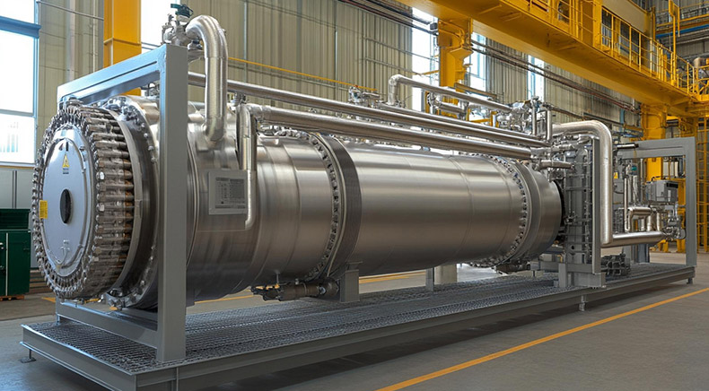
In process plants — whether in oil and gas, chemical, pharmaceutical, food processing, or power generation — vessels are containers designed to hold liquids, gases, or solids at various stages of a process. They are used for storage, reaction, separation, or heat exchange purposes. Depending on their function, they are categorized as:
- Storage Tanks: Hold raw materials or finished products.
- Reactors: Facilitate chemical reactions under controlled conditions.
- Separators: Divide mixtures into individual components.
- Drums and Knockout Pots: Remove liquids from gases or separate phases.
- Columns (Distillation, Absorbers): Separate components based on volatility.
P&ID – Vessel Symbols
Vessels come in many shapes and sizes-vertical or horizontal, cylindrical or spherical—and can be atmospheric or pressurized. Depending on their function and design, they require unique safety, control, and instrumentation considerations.
Why Vessel P&ID Symbols Matter?
Each vessel in a process must be clearly identified and represented within a P&ID to ensure:
- Clear communication across multi-disciplinary teams.
- Standardized documentation for construction and operations.
- Efficient troubleshooting and maintenance planning.
- Easier handover from design to commissioning to operation.
- Correct interpretation of function and operation
- Accurate instrumentation and control system design
- Effective maintenance and operational readiness
- Regulatory compliance and safety assurance
To standardize this representation, industries adhere to established conventions and standards like ISA S5.1, ISO 10628, and PIP (Process Industry Practices) when creating P&IDs. These standards define the symbols used to depict various types of vessels and associated components.
Now let’s explore the detailed representation of P&ID vessel symbols that we consider;
| Type of Vessel | Supportive Icon | Message |
|---|---|---|
| Vertical Vessel |  |
Upright cylindrical vessel for process containment. |
| Mixing Vessel | 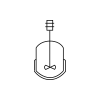 |
Vessel with an agitator for fluid blending. |
| Column |  |
Tall vessel for distillation or separation processes. |
| Tray Column |  |
Column with trays for staged phase separation. |
| Fluidized Bed Column | 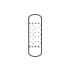 |
Column with suspended solid particles by gas. |
| Staggered Baffle Trays Column | 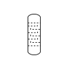 |
Column with alternating trays for efficiency. |
| Packing Column | 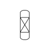 |
Column with internal packing for contact area. |
| Packing Column Repetition | 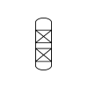 |
Packed internals for separation processes. |
| Drum |  |
Horizontal vessel used for phase separation. |
| Knock-out Drum | 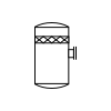 |
Removes liquids from gas stream. |
| Bag |  |
Flexible container used for temporary storage. |
| Bag (ISO) |  |
Standardized flexible vessel for dry bulk. |
| Barrel |  |
Cylindrical container used for liquid storage. |
| Barrel (ISO) |  |
ISO-defined drum for fluid containment. |
| Gas Bottle |  |
Small pressurized container for gas storage. |
| Boiler |  |
Heats water to produce steam energy. |
| Dome Boiler |  |
Boiler with domed top for steam. |
| Hot Liquid Boiler |  |
Heats liquid instead of creating steam. |
| Tank 1 |  |
Vertical tank, nozzle top, holds process fluid. |
| Tank 2 |  |
Sloped roof tank, stores liquid, non-pressurized fluid. |
| Tank 3 |  |
Open-top tank, stepped base, collects plant effluent. |
| Tank 4 |  |
Dished tank, top nozzle, mixes chemical batches. |
| Open Tank |  |
Tank exposed to atmosphere for liquids. |
| Covered Tank |  |
Enclosed tank to prevent contamination. |
| Floating Roof Tank |  |
Roof floats on liquid to reduce vapor. |
| Open Bulk Storage |  |
Uncovered vessel for storing large volumes. |
| Dome Roof Tank |  |
Tank with dome-shaped fixed roof. |
| Cone Roof Tank |  |
Conical roof tank for product containment. |
| Internal Floating Roof Tank |  |
Sealed tank with internal floating roof. |
| Double Wall Tank |  |
Secondary containment for leak prevention. |
| Onion Tank |  |
Flexible self-supporting tank for quick deployment. |
| Thermal Insulation Vessel |  |
Vessel protected against heat loss/gain. |
| Heating cooling Jacket Vessel |  |
Vessel with external thermal control jacket. |
| Brackets Vessel |  |
Vessel with support brackets for installation. |
| Dished Ends Vessel |  |
Vessel with curved ends for pressure. |
| Pit Vessel |  |
Installed below grade for drainage or containment. |
| Electrical Heating Vessel | 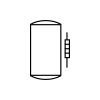 |
Heated using electric coils or plates. |
| Wastewater Treatment |  |
Tank for processing and treating wastewater. |
| Bin |  |
Container for storing dry bulk solids. |
Read this blog to learn what is Piping and Instrumentation Diagrams (P&ID), and their significance across diverse industries.
Additional Information Displayed with Vessel P&ID Symbols
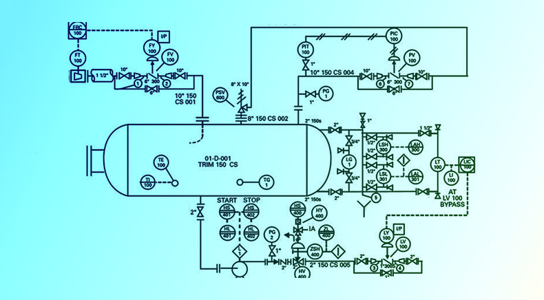
Simply using the right symbol is not enough. Engineers must annotate P&ID symbols fpr vessels with additional data to provide a complete picture. These include:
1. Tag Numbers
Every vessel in a P&ID has a unique tag number. This usually follows a format like:
- V:101: “V” stands for vessel, 101 is the identification number.
- T:205: “T” often used for tanks.
- R:301: “R” for reactors.
These tags connect to an equipment list that provides specifications.
2. Nozzles & Connections
Vessels will have small lines branching out representing:
- Inlets and outlets
- Overflow lines
- Vents and drains
- Relief valves
Each nozzle may include a reference for size, elevation, and direction.
3. Instrumentation Symbols
Vessels often include instrumentation for:
- Level control (Level Transmitter – LT)
- Temperature control (Temperature Indicator – TI)
- Pressure monitoring (Pressure Transmitter – PT)
- Flow indication (Flow Indicator – FI)
In a P&ID, these appear as circles with letters inside, connected to the vessel via dashed or solid lines.
4. Insulation, Lining, and Internal Components
- Dotted lines may show internal baffles, trays, or packing.
- External dashed lines may indicate insulation.
- Notes often mention lining material or special coatings (e.g., glass lining).
Best Practices When Reading or Creating Vessel Symbols in P&IDs
- Stick to Standard Conventions: Use ISO, ANSI/ISA, or client-specific legend sheets to ensure symbols match accepted standards.
- Consistency is Key: Across all P&IDs in a project, ensure that the same symbol style is used for similar equipment.
- Avoid Overcomplication: A symbol doesn’t need to show every mechanical detail—only those necessary for understanding process operation and control.
- Use Cross – Referencing Efficiently: Use tag numbers and line identifiers to cross reference vessels with other drawings, datasheets, and specifications.
- Consult the Legend Sheet: Always refer to the project specific symbol legend to understand customized symbols or notations.
Role of Multidisciplinary Engineering in P&ID Development
Developing and interpreting vessel symbols is not only the domain of process engineers. It requires input from multiple disciplines:
- Mechanical Engineering: Ensures pressure vessel design matches symbol intent.
- Instrumentation & Control: Ensures correct placement of transmitters, sensors, and valves.
- Piping Engineering: Manages connectivity, nozzle locations, and routing.
- Safety Engineering: Confirms that relief devices and vents are appropriately represented.
A multidisciplinary design engineering company like Rishabh Pro Engineering brings together experts from all these domains, ensuring that P&IDs—including vessel symbols—are technically sound, code compliant, and project specific.
Final Words
Understanding P&ID vessel symbols involves more than just deciphering icons; it also entails making sure that every stage of a project is clear and consistent. Accurate depictions of process vessels are essential for efficient engineering communication at every stage, from design and installation to troubleshooting and audits. Through collaboration with a multidisciplinary team providing equipment engineering services, businesses can guarantee that their P&IDs are both technically sound and prepared for the future. At Rishabh Pro Engineering, we provide strong documentation that improves project performance, safety, and compliance thanks to our proficiency in vessel design, process integration, and cross-disciplinary collaboration. This helps clients maintain their competitiveness in an increasingly demanding industrial environment.