
Piping and Instrumentation Diagrams (P&ID): A Comprehensive Guide
In the complex world of process industries, effective communication and documentation are crucial for ensuring safety, efficiency, and successful operation. The Piping and Instrumentation Diagram (P&ID) is vital in this domain. With this article, we will explore what is P&ID, its significance across diverse industries, the symbols employed, and a comprehensive guide on crafting them.
What is a Piping and Instrumentation Diagram?
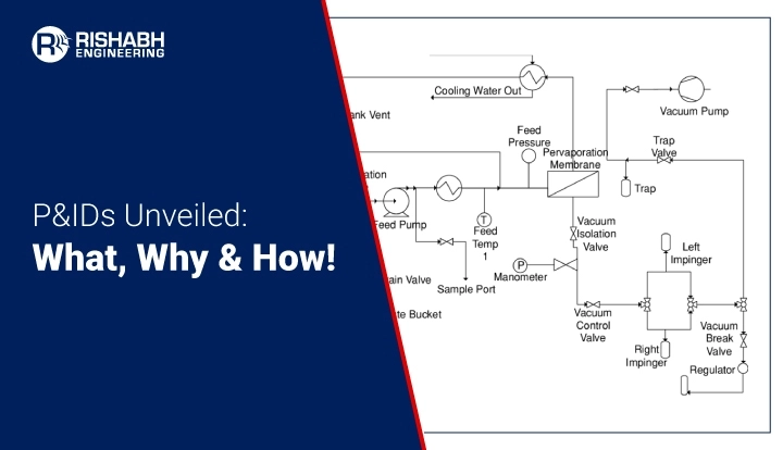
P&ID is a schematic representation that illustrates the interconnection of process equipment and the instrumentation used to control the processes in a facility. A Piping and Instrumentation Diagram (P&ID) is an intricate visual depiction of the system’s components, including piping, instruments, valves, pumps, and various equipment. P&IDs offer standardized and detailed means of visually representing intricate processes, assisting engineers, operators, and stakeholders in comprehending the design and functionality of the system.
What Does P&ID Include?
Based on our experience, a comprehensive P&ID must include;
- Numerically listed mechanical machinery
- Valves with identifications
- Process piping, sizes, and identification
- Miscellaneous items like vents, drains, special fittings, sampling lines, reducers, increasers, and swagger
- Permanent start-up, flush edges, and flow directions
- Interconnections reference, control inputs, and output interlock
- Seismic category and annunciation inputs
- Computer control system input
- Vendor and contractor interfaces
- Identifications for outsourced components and subsystems
- The estimated physical sequence of equipment and its rating or capability
Importance of P&ID
- Communication and Understanding: P&IDs are a universal language in engineering. They facilitate effective communication between disciplines, such as process engineers, instrumentation specialists, and operators. With standardized representation, everyone involved can easily comprehend the design and functionality of a system.
- Safety: For process industries, P&IDs play a crucial role in ensuring the safety of personnel and equipment by clearly depicting the location and operation of safety-critical elements, such as relief valves, emergency shutdown systems, and isolation valves.
- Operational Efficiency: Understanding the process flow and equipment interconnections is essential for optimizing operations. P&IDs help operators identify the sequence of operations, monitor equipment status, and troubleshoot issues efficiently.
- Maintenance and Modification: P&IDs serve as a valuable reference during maintenance activities and system modifications. They provide a comprehensive system overview, aiding maintenance personnel in identifying equipment, isolating sections, and planning modifications without compromising safety or efficiency.
Limitations of P&IDs
P&IDs have limitations, such as potential complexity leading to comprehension challenges, static representation without real-time data, and the risk of becoming outdated due to system modifications. They may lack intuitive 3D spatial information, hindering visualization. Additionally, P&IDs might not capture dynamic process behaviors or account for human factors. Their effectiveness depends on the accuracy of initial design information and the diligence of updates, making them susceptible to errors and inconsistencies in evolving industrial environments.
How To Read P&IDs?
P&IDs are essential tools in the engineering and manufacturing industries. Reading P&IDs is crucial for understanding the process flow in industrial plants. Start by identifying major equipment such as pumps, tanks, and vessels. Follow the flow of piping, noting valves, instruments, and fittings. P&IDs use symbols to represent components, with arrows indicating the flow direction. Dotted lines may represent secondary systems like utilities.
Study the symbols legend to interpret valves (control, check), instruments (flow meters, pressure gauges), and equipment. Lines with letters (P, T, F) denote process variables (Pressure, Temperature, Flow). Pay attention to instrumentation tags for details on each device. Identify control loops and interlocks, often depicted by feedback lines and symbols.
Understanding the symbols, flow direction, and equipment relationships helps interpret the entire process. P&IDs are essential for design, operation, and troubleshooting in chemical, petrochemical, and manufacturing industries. Regular practice enhances proficiency in reading and comprehending these diagrams.
Piping and Instrumentation Diagram Symbols
P&IDs use a standardized set of symbols to represent various components and instruments. Understanding these symbols is essential for interpreting the diagrams accurately. Here are some common P&ID symbols:
Piping Symbols
A pipe serves as a conduit for transporting fluids. Piping comes in different materials, such as metal and plastic. The piping assembly includes individual, multiple-line, separators, and other piping devices.
- Straight Line: Represents a pipe.
- Elbow: Indicates a change in the direction of the pipe.
- Valve: Represents a valve used to control fluid flow.
- Flange: Depicts a connection point between pipes.
Listed below are the piping p&id symbols we consider;

Vessel Symbols
A vessel serves as a receptacle designed for holding fluids, with the potential to modify the fluid’s characteristics over storage. This category encompasses tanks, cylinders, columns, bags, and various other types of containers.
Listed below are the vessel symbols we consider;

Heat Exchanger Symbols
A heat exchanger efficiently transfers heat between different areas or mediums. Examples within this category include boilers, condensers, and other heat exchangers.
Listed below are the heat exchanger symbols we consider;

Pump Symbols
A heat exchanger efficiently transfers heat between different areas or mediums. Examples within this category include boilers, condensers, and other heat exchangers.
Listed below are the ones we consider;

Instrument Symbols
An instrument measures and occasionally regulates quantities like flow, temperature, angle, or pressure. You’ll find indicators, transmitters, recorders, controllers, and elements within the instrument category.
- Circle: Represents an instrument, such as a pressure transmitter or flow sensor.
- Square: Indicates an indicator, recorder, or controller.
- Triangle: Depicts a transmitter or detector.
Listed below are the ones we consider;

Equipment Symbols
The equipment category consists of various P&ID units that do not fall under other specified categories. This group encompasses hardware such as compressors, conveyors, motors, turbines, vacuums, and other mechanical devices.
- Circle with a Cross Inside: Represents a heat exchanger.
- Rectangle: Depicts equipment such as tanks or vessels.
- Pump Symbol: Represents a pump used to move fluids.
Listed below are the ones we consider;

Valve Symbols
A valve manages fluid flow in a piping system by opening, closing, or partially obstructing passageways. This group encompasses rotameters, orifices, and various other valve types.
Listed below are the valve symbols we consider;

How Do You Create A Piping And Instrumentation Diagram?
Creating a P&ID involves several steps, from gathering information about the process to producing the final diagram. Here’s a step-by-step guide:
- Gather Information: Collect data on the process, including equipment specifications, instrumentation details, and process flow information.
- Identify Components: List all the equipment, pipes, valves, instruments, and other components involved.
- Define Symbols and Codes: Establish a set of symbols and codes that will be used consistently throughout the diagram.
- Create a Draft: Begin sketching a rough draft of the P&ID. Place equipment and components in their approximate locations and connect them with lines to represent piping.
- Add Detail: Refine the draft by adding instrument symbols, valve types, and other details. Different line types represent various pipe materials and indicate the flow direction.
- Review and Revise: Review the draft with stakeholders, including process engineers, operators, and safety personnel. Revise the diagram based on feedback and ensure it accurately represents the system.
- Finalize the P&ID: Produce the final P&ID using computer-aided design (CAD) software or specialized P&ID tools. Ensure that it adheres to industry standards and is easily understandable by anyone familiar with P&ID conventions.
Role of Multidisciplinary Engineering With P&ID Development
Organizations like Rishabh Engineering play a crucial role in supporting the development of P&IDs, especially in large and complex projects. Here’s how a multidiscipline engineering company can assist you:
- Expertise Across Disciplines: Multidisciplinary engineering firms have expertise in various engineering disciplines, including process, mechanical, electrical, and instrumentation. This broad knowledge ensures a comprehensive and integrated approach to P&ID development.
- Intelligent P&ID: The reciprocal exchange of data between P&ID graphics and the centralized database offers a robust tool for design and management, particularly in the initial phases of process and instrumentation design. The client team and Rishabh Engineering gain real-time access to updated graphics and reports as project team members, facility technicians, and maintenance personnel contribute input and modifications. This dynamic interaction ensures that P&IDs are a reliable groundwork for developing comprehensive process management systems and procedures. Thus reducing the human error in extracting BOQ at various stages and making them accurate. Using intelligent P&ID data, Rishabh Engineering facilitates automated report generation at various facility development and management stages. This includes producing reports during design, construction, maintenance, and overall facility oversight. The generated reports encompass diverse categories such as equipment lists, equipment specification sheets, line lists, manual and automatic valve lists, motor lists, and instrumentation lists. Rishabh Engineering ensures adaptability by offering customized reports in formats specified by end users. The system is supported by flexible and expandable databases integrated into a tailored Microsoft® Access or related database. Online updates are seamlessly incorporated into existing reports, reflecting the most recent data revisions. The bidirectional updating feature ensures synchronization between drawings and the project database. The efficiency is further enhanced as a single data entry is automatically propagated throughout the project database.
- Special Requirement P&IDs: Our team excels in crafting special requirement P&IDs. Drawing on extensive design experience, they create P&IDs adhering to global standards while tailoring solutions to meet the specific needs of major O&G companies such as Chevron, BP, ADNOC, and others. Rishabh’s proficiency ensures the seamless integration of industry-specific requirements into the design process, offering a comprehensive and compliant solution for diverse projects in the oil and gas sector.
- Efficient Collaboration: P&ID development often involves collaboration among different engineering disciplines. Multidisciplinary firms facilitate efficient communication and coordination among teams, minimizing the risk of errors and ensuring a cohesive design.
- Compliance and Standards: Engineering companies like Rishabh Engineering are well-versed in industry standards and regulatory requirements. They can ensure that P&IDs comply with relevant local and global standards, codes, and regulations, including P&ID legends and representation for ISO, BS, DIN, and more. This helps reduce the likelihood of compliance-related issues.
- As-built P&ID: Our P&ID administrators have almost decades of industry experience and an in-depth understanding of engineering support and design activities while utilizing multiple software and technologies. They can help collect data at sight (with fresh data capture or updating old data based on collected data from the site). It is by utilizing either manual or laser scan capture. Our engineering support technicians excel in project setup and offer automation through SQL queries and Llama programming. Further, the subject matter experts carry out updates for PFD and P&ID.
Final Words
P&IDs are indispensable tools in process industries, providing a standardized and visual representation of complex systems. From enhancing communication and safety to optimizing operations and facilitating maintenance, P&IDs play a vital role in every stage of a facility’s lifecycle. Understanding the symbols used in P&IDs and following a systematic approach to their creation ensures that these diagrams serve their intended purpose effectively, contributing to the success and efficiency of industrial processes.
Frequently Asked Questions
Q. What are P&ID Use Cases?
A. Listed below are essential applications of P&IDs across engineering and industrial processes.
- Design and Planning: P&IDs are fundamental for conceptualizing and planning processes in chemical, petrochemical, and manufacturing industries. They visually represent equipment, piping, instrumentation, and flow direction.
- Engineering: During the detailed engineering phase, P&IDs serve as a guide for engineers. They help in sizing equipment, selecting instrumentation, and designing piping layouts.
- Communication: P&IDs are a universal language in the engineering domain. They facilitate stakeholder communication, including engineers, operators, and maintenance personnel.
- Safety: P&IDs are crucial in hazard analysis and ensuring safety protocols. They help identify potential risks and guide the implementation of safety measures.
- Operational Support: In day-to-day operations, P&IDs assist operators in understanding the process flow, monitoring equipment status, and troubleshooting issues.
- Maintenance and Upgrades: P&IDs are valuable for maintenance teams. They aid in identifying equipment, understanding connections, and planning modifications or upgrades.
- Regulatory Compliance: Industries often need to comply with regulations. P&IDs help in documenting processes and ensure that they meet regulatory standards.
- Training: P&IDs serve as educational tools for training operators and new personnel. They provide a visual overview of the entire process, aiding in understanding and learning.
Need Help With P&IDs?
Elevate your engineering skills by developing P&IDs with us. We consider diverse symbols for safety and efficiency, ensuring excellence in your industrial processes.
Related Blogs
Related Blogs
Detailed Engineering Considerations for Project Success
Engineering projects today require meticulous planning and execution across various…

Navigating the Green Hydrogen Value Chain
Green hydrogen is a powerful contender for a more sustainable…

Green Hydrogen Production Challenges & Solutions
Hydrogen, mainly green hydrogen, has emerged as a beacon of…