Pressure vessel design often begins with ASME code equations that help determine wall thickness, reinforcement requirements, and allowable stress for standard vessel configurations. While these Design-by-Rule methods are effective for conventional applications, they become less reliable when dealing with large openings, thin-wall vessels, complex nozzle arrangements, cryogenic operating conditions, or significant external loads. Such scenarios can create stress patterns that simplified calculations cannot accurately predict.
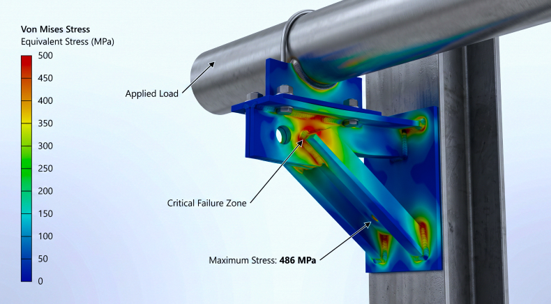
In these situations, engineers rely on finite element analysis of pressure vessels to evaluate actual stress distributions, deformation behavior, fatigue life, and structural stability. Unlike traditional calculations, pressure vessel finite element analysis provides deeper insight into real-world operating conditions and complex geometries, enabling more informed and code-compliant design decisions.
In this blog, we explore when pressure vessel FEA becomes necessary, key ASME requirements, common analysis types, industry standards, real-world project applications, and Rishabh Pro Engineering’s FEA-driven design methodology.
Design by Rule vs. Design by Analysis: What ASME Section VIII Actually Says
ASME Section VIII provides two primary approaches for pressure vessel design:
Design by Rule (DBR)
It is the traditional methodology used in ASME Section VIII Division 1. The code provides explicit equations for determining minimum required thicknesses, reinforcement areas, and allowable stresses based on standardized vessel geometries.
DBR works effectively when:
- Geometries remain within code assumptions
- Loading conditions are straightforward
- Stress concentrations are predictable
- Fatigue is not a governing design concern
For most standard pressure vessels, Division 1 remains the preferred approach because of its simplicity and industry acceptance.
Design by Analysis (DBA)
ASME Section VIII Division 2 Part 5 introduces Design by Analysis. Instead of relying solely on code equations, engineers perform detailed numerical analysis, including FEA analysis of pressure vessels, to evaluate structural behavior.
Design by Analysis becomes advantageous when:
- Geometry is complex
- Local stress concentrations govern design
- Fatigue assessment is required
- External pressure stability must be demonstrated
- Thermal gradients produce significant stress
- Transportation and installation loads influence vessel integrity
Design by Rule vs. Design by Analysis
| Parameter | Design by Rule (DBR) | Design by Analysis (DBA) |
| Governing Code | ASME Section VIII Div. 1 | ASME Section VIII Div. 2 Part 5 |
| Design Method | Formula-based calculations | Finite Element Analysis (FEA) |
| Geometry Complexity | Standard vessel configurations | Complex and non-standard geometries |
| Stress Evaluation | Simplified code equations | Detailed stress distribution assessment |
| Fatigue Assessment | Typically not required | Mandatory screening and evaluation |
| Nozzle Analysis | WRC methods and code equations | Detailed local stress analysis |
| Buckling Evaluation | Empirical code methods | Eigenvalue and nonlinear buckling analysis |
| Thermal Gradients | Limited assessment capability | Detailed thermal stress evaluation |
| Design Optimization | Conservative by nature | Allows weight and material optimization |
| Typical Application | Conventional pressure vessels | High-pressure, cyclic, cryogenic, or specialized equipment |
Design by Rule remains suitable for most standard pressure vessels. However, when equipment contains large nozzles, fatigue loading, cryogenic conditions, external pressure requirements, or complex geometries, Design by Analysis supported by pressure vessel FEA provides a more accurate representation of actual structural behavior.
When is FEA Elected?
Engineers may voluntarily choose finite element analysis of pressure vessels when conventional calculations become overly conservative or insufficient to represent actual conditions.
Common examples include:
- Large nozzles
- Integrally reinforced connections
- Specialized support systems
- Custom process equipment
- Thick-to-thin section transitions
When is FEA Required?
Certain configurations effectively necessitate FEA of pressure vessels because design-by-rule calculations cannot adequately characterize stress distributions.
Examples include:
- Complex local discontinuities
- High cyclic loading applications
- Advanced fatigue assessments
- Buckling-sensitive structures
- Detailed local stress categorization
The Fatigue Screening Requirement
One important consequence of adopting ASME Section VIII Division 2 is fatigue evaluation. Even when primary membrane stresses satisfy allowable limits, Division 2 requires fatigue screening to determine whether cyclic service conditions demand a detailed fatigue assessment. If screening thresholds are exceeded, fatigue analysis becomes mandatory. As a result, pressure vessel finite element analysis often becomes a necessary component of Division 2 compliance rather than simply an optional verification exercise.
FEA Trigger Conditions in Pressure Vessel and Piping Projects
Several engineering conditions commonly trigger the need for pressure vessel FEA analysis.
- D/t Ratio Greater Than 100: Thin-wall vessels become increasingly susceptible to local deformation and instability, making finite element analysis of pressure vessels valuable for accurate stress assessment.
- Branch Connections with d/D Greater Than 0.5: Large branch openings create significant local stress concentrations that exceed the applicability limits of many empirical reinforcement methods.
- External Pressure Design: Buckling rather than yielding often governs design under vacuum or external pressure conditions, requiring numerical stability analysis.
- Fatigue Service: Repeated pressure, temperature, vibration, or operational cycles necessitate fatigue assessment using stress ranges obtained from FEA.
- Cryogenic Applications: Large thermal gradients and material property changes at low temperatures require detailed thermal-stress evaluation.
- Transportation and Lifting Loads: Pressure vessels experience temporary but significant loads during transportation, lifting, and installation that are not covered by standard pressure design equations.
- Weld Joints and Attachments: Complex welded details frequently create localized peak stresses that require detailed numerical assessment.
- Shell-to-Head Transitions: Geometric discontinuities at shell-head intersections can generate secondary stresses requiring stress linearization and classification.
- Nozzle-to-Shell Intersections: Nozzle loads from connected piping systems often produce local stresses beyond the scope of traditional calculations.
Core Types of Pressure Vessel Finite Element Analysis
Stress Linearization Analysis
Stress linearization forms the foundation of ASME Division 2 assessment procedures.
Engineers classify stresses into:
- Primary membrane stress
- Primary bending stress
- Secondary stress
- Peak stress
This categorization helps determine code compliance while avoiding overly conservative interpretations of localized stress concentrations. Stress linearization is among the most common forms of pressure vessel FEA used in code-based assessments.
Governing Standards
- ASME Section VIII Division 2 Part 5 – Defines stress categorization, stress linearization procedures, and acceptance criteria for Design-by-Analysis.
- ASME Section II – Provides material properties and allowable stress values used during FEA evaluation.
Thermal Stress Analysis
Temperature gradients can generate stresses comparable to or greater than pressure loads.
Thermal analysis evaluates:
- Start-up conditions
- Shutdown conditions
- Transient operations
- Heat exchanger effects
- Cryogenic cooling scenarios
The resulting temperature distribution becomes the basis for structural stress calculations.
Governing Standards
- ASME Section VIII Division 2 Part 5 – Establishes requirements for evaluating thermal stresses and their impact on vessel integrity.
- ASME B31.3 – Governs thermal expansion and flexibility considerations in connected process piping systems.
- API 579-1/ASME FFS-1 – Provides procedures for assessing equipment exposed to thermal damage or elevated temperature service.
- EN 13445 – Includes Design-by-Analysis provisions for thermal loading in unfired pressure vessels.
Buckling Analysis
Buckling analysis determines the stability of structures subjected to compressive loads.
Typical applications include:
- Vacuum vessels
- Tall columns
- Storage tanks
- Jacketed vessels
- Thin-wall pressure equipment
Eigenvalue and nonlinear buckling analyses are commonly performed depending on project requirements.
Governing Standards
- ASME Section VIII Division 2 Part 5.4 – Defines elastic-plastic buckling assessment methods and acceptance criteria.
- ASME Section VIII Division 1 – Provides Design-by-Rule procedures for vessels subjected to external pressure.
- EN 13445 – Contains stability assessment requirements for pressure-retaining equipment.
- API 650 and API 620 – Govern buckling and stability considerations for atmospheric and low-pressure storage tanks.
Fatigue Analysis
Fatigue analysis evaluates cumulative damage resulting from cyclic loading.
Engineers use:
- Stress ranges
- Cycle counts
- Material fatigue curves
- ASME fatigue design curves
This form of finite element analysis of pressure vessels is especially important in hydrogen, cryogenic, power generation, and cyclic process applications.
Governing Standards
- ASME Section VIII Division 2 Part 5.5 – Provides fatigue screening methods, fatigue curves, and cumulative damage assessment procedures.
- ASME BPVC Section VIII – Defines cyclic service requirements for pressure-retaining equipment.
- API 579-1/ASME FFS-1 Part 14 – Used to evaluate remaining fatigue life of equipment already in service.
- EN 13445 – Includes fatigue design rules for vessels operating under repeated loading cycles.
Seismic Analysis
Facilities located in seismic regions require evaluation of earthquake-induced loads.
FEA Analysis of pressure vessels helps determine:
- Base reactions
- Stress distribution
- Support adequacy
- Structural stability
Industry standards such as ASCE 7 and site-specific seismic criteria often govern these evaluations.
Governing Standards
- ASCE 7 – Establishes seismic load calculations, response spectra, and load combinations for equipment and structures.
- ASME Section VIII – Ensures pressure vessel integrity under seismic loading conditions.
- International Building Code (IBC) – References seismic design requirements based on geographic location and occupancy.
- Project-Specific Seismic Criteria – May include owner, EPC, or regulatory requirements beyond minimum code provisions.
Nozzle Load Analysis
Piping systems transfer forces and moments to vessel nozzles.
Engineers perform nozzle load assessments to verify:
- Local shell stresses
- Reinforcement adequacy
- Weld integrity
- Compliance with ASME criteria
Pressure vessel finite element analysis is frequently used when WRC methods fall outside their valid range.
Governing Standards
- ASME Section VIII Division 2 Part 5 – Provides Design-by-Analysis requirements for evaluating local stresses around nozzle-shell intersections.
- ASME B31.3 – Defines allowable piping loads and interaction requirements between piping systems and equipment nozzles.
- WRC Bulletin 537 – Current industry-standard method for evaluating local stresses caused by nozzle loads.
- WRC Bulletins 107 and 297 – Legacy analytical methods commonly used for preliminary nozzle stress assessments.
- API 579-1/ASME FFS-1 – Supports fitness-for-service evaluations when nozzle regions exhibit damage or elevated stresses.
Each type of pressure vessel FEA is governed by specific design codes and industry standards that define loading requirements, acceptance criteria, stress limits, and assessment methodologies. Selecting the appropriate standard is critical to ensuring both code compliance and long-term equipment reliability.
Rishabh Pro Engineering Methodology for FEA-Driven Pressure Vessel Design
Step 1: Engineering Requirement Definition
Every project begins with a detailed review of process conditions, design pressure, operating temperature, cyclic loading requirements, transportation constraints, and applicable codes. This stage establishes whether finite element analysis of pressure vessels is necessary and defines the required scope.
Step 2: Geometry Development and Model Setup
Engineers develop high-fidelity numerical models using project-specific vessel geometry.
Critical regions such as:
- Nozzles
- Supports
- Attachments
- Weld transitions
- Shell-head intersections
receive refined meshing to accurately capture local stress behavior.
Step 3: Boundary Condition Definition
Realistic operating conditions are applied to the model.
These may include:
- Internal pressure
- External pressure
- Thermal loads
- Wind loads
- Seismic loads
- Transportation accelerations
- Piping reactions
Accurate boundary conditions are essential for meaningful pressure vessel finite element analysis results.
Step 4: Code Alignment and Analysis Execution
The model is evaluated according to the governing standards.
Engineers perform:
- Stress linearization
- Fatigue screening
- Buckling assessment
- Thermal evaluation
- Structural verification
All acceptance criteria are aligned with applicable ASME and industry requirements.
Step 5: Results Interpretation and Design Optimization
Analysis results are reviewed beyond simple maximum stress values.
Engineers evaluate:
- Stress categories
- Load paths
- Fatigue margins
- Stability margins
- Deflection behavior
Where required, design improvements are introduced to optimize safety, constructability, and cost.
Step 6: Multidisciplinary Handoff
The final analysis outputs are integrated with piping, structural, process, and fabrication teams.
This coordinated approach ensures that FEA findings translate into practical engineering decisions and manufacturable designs.
How Rishabh Pro Engineering Approaches Pressure Vessel FEA: Projects and What They Solved
Case 1: Equipment Nozzles and Piping Stress Finite Element Analysis
For a process plant project, Rishabh Pro Engineering performed finite element analysis to evaluate localized stresses at equipment nozzles subjected to piping loads. The assessment helped verify nozzle integrity, identify critical stress concentrations, and ensure compliance with pressure vessel and piping design requirements.
Type of FEA Performed
- Nozzle load analysis
- Local stress assessment
- Finite element stress analysis
Standards Applied
- ASME Section VIII Division 2
- ASME B31.3
Software Used
- ANSYS
- CAESAR II
Outcome
The analysis validated nozzle design under applied piping loads, identified critical stress regions, and supported code-compliant design modifications where required.
Case 2: Structural Stress Analysis of Flare Stack
For a refinery flare stack system, Rishabh Pro Engineering performed finite element-based structural analysis to evaluate stress distribution, deflection behavior, and stability under combined operational and environmental loading conditions. The assessment focused on identifying critical stress locations within the flare structure and verifying its ability to withstand wind-induced loads while maintaining structural integrity.
Type of FEA Performed:
- Structural stress analysis
- Wind load-induced stress evaluation
- Deflection and stability assessment
Standards Applied
- ASCE 7
- AISC Steel Construction Standards
Software Used
- STAAD.Pro
Outcome
The structural stress analysis of the flare stack helped identify critical stress regions, verified compliance with design code requirements, and validated the flare stack’s structural performance under governing load combinations, ensuring safe and reliable operation throughout its design life.
Integrating Pressure Vessel FEA with ASME and Industry Standards
Finite element analysis must always be aligned with applicable design codes and standards.
- ASME Section VIII Division 1: Governs conventional design-by-rule pressure vessel calculations.
- ASME Section VIII Division 2 Part 5: Governs design-by-analysis procedures including stress categorization, fatigue, and buckling assessments.
- ASME Section II: Provides material properties required for numerical analysis.
- ASME B31.3: Governs process piping systems and associated nozzle loading interfaces.
- API 579-1 / ASME FFS-1: Used for fitness-for-service evaluations of existing equipment.
- API 650: Governs welded storage tanks where structural and stability assessments may be required.
- API 620: Applies to low-pressure and cryogenic storage tanks.
- EN 13445: European pressure vessel design standard supporting design-by-analysis methodologies.
- PD 5500: British pressure vessel code frequently used in international projects.
- ASCE 7: Defines environmental loads including wind and seismic requirements.
- NBIC: Provides guidance for inspection, repair, and alteration of pressure-retaining equipment.
Successful pressure vessel FEA analysis requires that numerical models satisfy the intent and acceptance criteria of the governing code rather than merely producing stress plots.
Concluding Thoughts
As pressure vessel designs become increasingly complex, traditional design-by-rule approaches alone may not always provide sufficient insight into structural behavior. Large openings, fatigue-sensitive service conditions, cryogenic temperatures, transportation loads, external pressure requirements, and non-standard geometries frequently demand a more detailed evaluation.
FEA of pressure vessels enables engineering teams to understand actual stress distributions, assess stability, evaluate fatigue life, and demonstrate compliance with modern design codes. When properly aligned with ASME Section VIII and other industry standards, finite element analysis of pressure vessels provides the confidence needed to validate challenging designs while maintaining safety and reliability.
Through our finite element analysis consulting services, Rishabh Pro Engineering combines Design-by-Analysis methodologies, industry standards, and advanced simulation tools to validate pressure vessel performance. The result is code-compliant, optimized equipment designed to withstand operational, thermal, and mechanical loading conditions throughout its service life.
Frequently Asked Questions (FAQs) On Pressure Vessel FEA
Q: What is finite element analysis of pressure vessels?
A: FEA of pressure vessels is a numerical simulation technique used to evaluate stress distribution, deformation, fatigue life, thermal behavior, and structural stability under operating and design load conditions. It helps engineers assess complex geometries that cannot be accurately evaluated using conventional code equations.
Q: When is pressure vessel FEA required?
A: Pressure vessel finite element analysis is typically required when equipment contains large openings, non-standard geometries, fatigue loading, external pressure conditions, cryogenic temperatures, transportation loads, or complex nozzle configurations that exceed the limitations of Design-by-Rule methods.
Q: What standards govern pressure vessel finite element analysis?
A: FEA analysis of pressure vessels is commonly performed in accordance with ASME Section VIII Division 2 Part 5. Additional standards such as ASME Section VIII Division 1, ASME B31.3, API 579-1/ASME FFS-1, API 620, API 650, EN 13445, and ASCE 7 may also apply depending on the project.
Q: What software is used for pressure vessel FEA analysis?
A: Engineers typically use software such as ANSYS Mechanical, Abaqus, PV Elite, NozzlePRO, SolidWorks Simulation, Autodesk Inventor Nastran, and other specialized finite element platforms for pressure vessel FEA. The software selection depends on project complexity, code requirements, and analysis objectives.
Q: What are the benefits of pressure vessel FEA?
A: FEA analysis of pressure vessels provides accurate stress assessment, improved fatigue evaluation, better buckling prediction, optimized material utilization, reduced overdesign, and enhanced confidence in code compliance. It is particularly valuable for complex process equipment operating under demanding service conditions.