Project Information
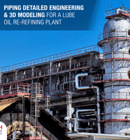
Aeraulic Plant Piping, Ducting and Support Design with Fabrication Drawings
Description
Client
A Europe-based advanced manufacturing company specializing in developing of wood-panels for industrial use using modern technology.
Engineering Requirement
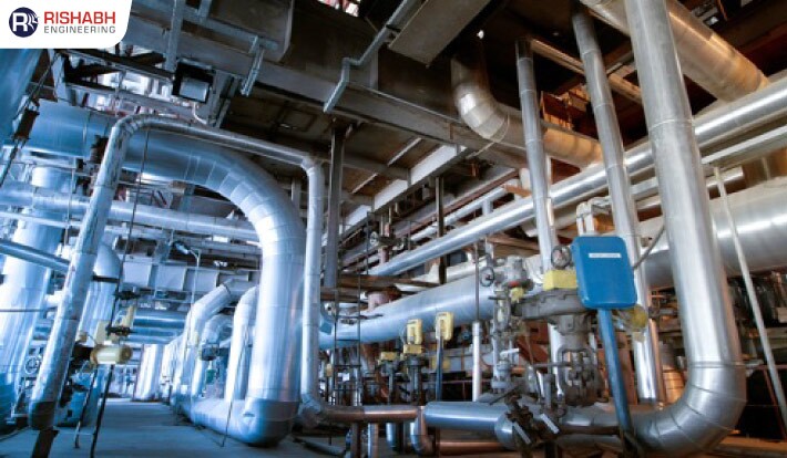
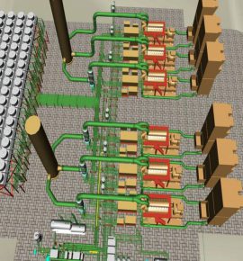
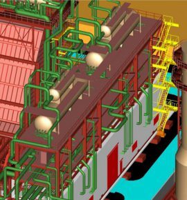
For their upcoming new plant, to ensure that the air is distributed evenly throughout the facility, they were in pursuit of an engineering partner who could help them with aeraulic piping layout – designing a piping network for air distribution systems.
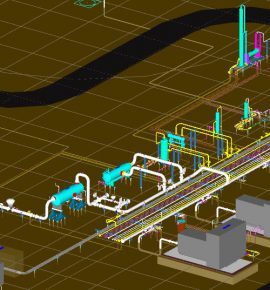
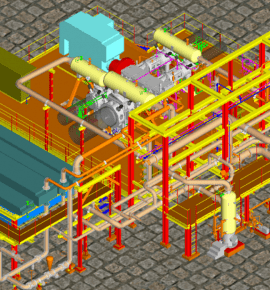
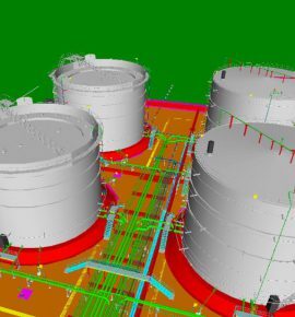
Appointed as the engineering design services partner, our job was to design and size aeraulic piping networks by utilizing SolidWorks. Based on the provided flowsheet, we create 3D models of all high-pressure piping and low-pressure ducting lines’ air transfer within the plant. Further, we developed detailed fabrication packages & general arrangement (GA) drawings to enable pipework installation.
Backed by advanced modeling tools and sophisticated software, the overall scope for this project included the following;
- Piping and ducting layout
- Fabrication detail drawings
- Flap Valve design and drawings
- GA drawings
- Bill of materials (Piping & Structural)
Want to know more about this project?
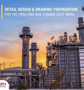
Our Recent Projects

Connect with us for all your engineering design needs
US Toll-Free Phone
+1-877-747-4224
India Phone
+91 8511122697
Drop Us An Email
sales@rishabheng.com
Our Offices
USA, UK & India (Head office)
Ready to work with us? Tell us more
Our Recent blogs