Finite Element Analysis (FEA) is widely used to evaluate how engineering components and systems respond to real-world loads before fabrication or modification. By simulating stress, deformation, thermal effects, and other structural responses, FEA helps engineers identify potential weaknesses and validate designs under defined operating conditions. For EPC projects, this provides valuable insight into the performance of equipment, piping interfaces, supports, structures, skids, and other critical components.
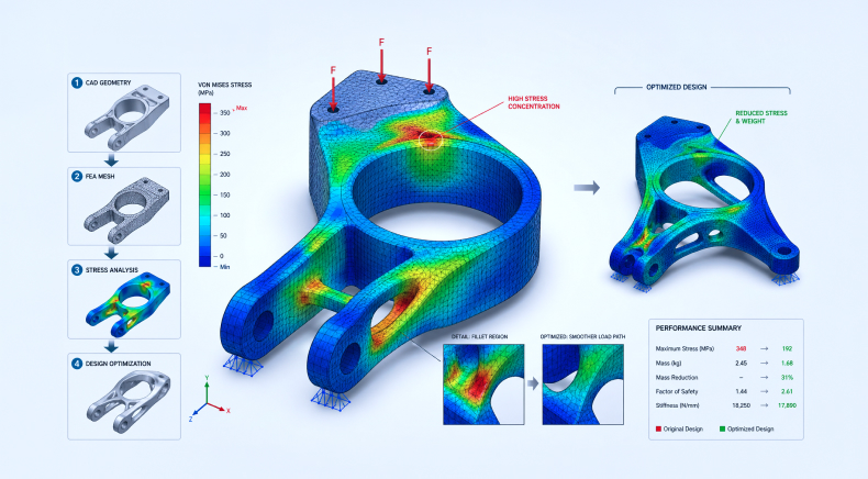
FEA optimization takes this analysis further by using simulation results to improve a design’s geometry, dimensions, material distribution, or structural configuration while maintaining the required performance and safety margins. Instead of relying solely on conservative assumptions or multiple physical iterations, engineers can compare design alternatives and make informed modifications.
Design optimization using FEA is particularly valuable for complex geometries, localized stresses, nonlinear behavior, thermal loading, contact conditions, and multiple load cases. However, optimization is not simply about reducing weight or material. The final design must also satisfy applicable codes, project specifications, operating conditions, fabrication requirements, and safety criteria.
In this blog, we’ll explore what FEA optimization is, why it matters for EPC projects, the key FEA optimization techniques, and the steps involved in implementing them. We’ll also look at how FEA supports process optimization across oil & gas, petrochemical, and power projects, and how Rishabh Pro Engineering can support your engineering requirements.
What Is FEA Optimization?
FEA optimization is the process of using Finite Element Analysis results to systematically improve the performance, geometry, material usage, or structural efficiency of an engineering design. A conventional FEA study determines how a component behaves under defined loads and boundary conditions. FEA Optimization builds on this by using the analysis results to identify opportunities for design improvement. Depending on the engineering objective, variables such as thickness, dimensions, geometry, material distribution, or structural configuration can be modified and evaluated through multiple iterations.
FEM optimization, or Finite Element Method optimization, refers to the same broader concept from the perspective of the numerical method used to perform the analysis. FEA and FEM are often used interchangeably in engineering discussions, although FEM describes the underlying numerical method while FEA generally refers to its engineering application.
For industrial projects, optimization should not be treated as an isolated software exercise. The final design must be reviewed against applicable codes, client specifications, material properties, fabrication constraints, load cases, and service conditions.
For example, pressure equipment may require consideration of ASME Section VIII, while process piping interfaces may involve ASME B31.3. Depending on the equipment and application, other standards such as API 579-1/ASME FFS-1, EN 13445, WRC guidelines, or project-specific specifications may also influence the assessment.
Why FEA Design Optimization Matters for EPCs
For EPCs, design decisions have consequences across engineering, procurement, fabrication, construction, commissioning, and operation. A design that appears acceptable during preliminary engineering may require refinement once detailed loads, interfaces, operating conditions, or fabrication constraints are established.
FEA design optimization helps engineering teams make these decisions earlier and with greater confidence.
- Design Revalidation: FEA can be used to reassess an existing design when operating conditions, loads, geometry, materials, or project requirements change. This is particularly relevant during detailed engineering, design modifications, revamps, and brownfield projects.
- Predictive Performance Assessment: Simulation enables engineers to evaluate stress, strain, deformation, buckling, thermal response, and other structural behaviors before physical fabrication or modification. This allows potential weak areas to be identified earlier in the project lifecycle.
- Material and Weight Efficiency: Optimization can identify areas where material is underutilized and where thickness, geometry, or structural configuration can be adjusted. For EPC projects, this can contribute to reduced equipment weight, material consumption, fabrication requirements, and transportation loads.
- Complex Geometry Evaluation: Components with openings, nozzles, fillets, local reinforcements, supports, connections, lifting arrangements, or irregular geometry may require more detailed analysis than conventional hand calculations can provide.
- Risk Reduction: By evaluating critical loading scenarios and localized behavior, FEA can help engineers identify potential failure locations and design weaknesses before they become fabrication or operational issues.
- Code and Design Compliance: FEA results can support design-by-analysis and engineering validation when used with the applicable code methodology. For pressure equipment, for example, ASME Section VIII Division 2 includes design-by-analysis requirements, while WRC guidance may be relevant for localized stresses around vessel nozzles and attachments.
- Faster Design Iterations: A simulation-driven workflow allows engineering teams to compare alternatives without relying exclusively on physical prototypes. This is particularly useful when several design iterations are expected during detailed engineering.
FEA Optimization Techniques
FEA optimization techniques help engineers refine designs based on specific performance and engineering objectives. The appropriate technique depends on the design stage, geometry, loading conditions, and desired outcome. From optimizing material distribution in early concepts to refining geometry and component dimensions in detailed design, these methods provide a structured approach to improving structural performance and efficiency.
| Technique | Design Stage | What It Optimizes | Typical Output | Best Use Case |
| Topology Optimization | Conceptual / early design | Material distribution and structural load paths | Optimized material layout / conceptual geometry | Weight reduction and new component concepts |
| Shape Optimization | Detailed design | Geometry and surface profile | Refined geometry with improved stress distribution | Reducing stress concentrations and improving structural behavior |
| Sizing Optimization | Detailed / final design | Thickness, dimensions, cross-sections | Optimized member or component dimensions | Weight and material optimization of established designs |
Topology Optimization
Topology optimization determines where material is structurally necessary within a defined design space. The method can help engineers understand efficient load paths and identify areas where material can potentially be removed without significantly affecting structural performance. It is generally most useful during the conceptual or early design stage, particularly when developing a new component or evaluating significant weight-reduction opportunities.
The resulting geometry normally requires engineering refinement for manufacturability, fabrication access, inspection, joining methods, and applicable design requirements before it can become a final production design.
Shape Optimization
Shape optimization focuses on modifying the geometry of an existing component to improve its structural response. It can be used to address localized stress concentrations around changes in geometry, openings, corners, fillets, transitions, or other critical regions. Depending on the problem, both linear and nonlinear FEA may be required.
For industrial equipment, shape optimization can be useful when the overall component configuration is already established but localized geometry needs to be refined to achieve better stress distribution or performance.
Sizing Optimization
Sizing optimization modifies established geometric parameters such as thickness, diameter, cross-section, or reinforcement dimensions. This approach is particularly useful when the design configuration is already defined, and the engineering objective is to achieve the required strength or stiffness with efficient material usage.
For example, an engineering team may evaluate different plate thicknesses, stiffener dimensions, reinforcement sizes, or structural member sections and select an appropriate configuration based on stress, deformation, stability, fabrication, and code requirements.
Steps for Design Optimization Using FEA
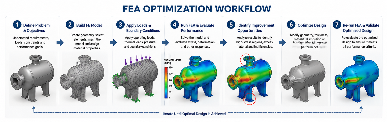
An effective FEA optimization workflow requires more than running a model and selecting the lowest stress result. The quality of the outcome depends on the engineering assumptions, model idealization, boundary conditions, mesh strategy, convergence, interpretation of results, and subsequent design verification.
Step 1: Simplify the Model
The first step is to prepare the model for analysis by retaining the geometry and components relevant to the engineering question.
Unnecessary small features, cosmetic details, threads, logos, or geometry that has no meaningful influence on the response may be removed. However, features that influence stress concentration, stiffness, contact, load transfer, or local behavior should be retained.
The level of simplification depends on the objective of the analysis. A global structural assessment may permit greater geometric idealization, whereas a local nozzle, lug, support, or connection assessment may require detailed representation of the critical region.
Step 2: Define Loads and Boundary Conditions
Loads, supports, constraints, contacts, temperatures, pressures, and other relevant operating conditions are defined based on the project design basis.
Engineering judgment is critical at this stage because unrealistic constraints or load application can produce misleading results.
For EPC projects, load inputs may originate from multiple disciplines. For example, piping loads may be obtained from piping stress analysis and subsequently applied to equipment nozzles or supports. Rishabh Pro Engineering follows this multidisciplinary approach when performing piping stress and FEA assessments for equipment interfaces. Applicable load combinations and design conditions are established based on project requirements and relevant codes.
Step 3: Generate the Mesh
Mesh selection is one of the most important parts of an FEA study because the mesh determines how accurately the numerical model represents the physical component.
At Rishabh Pro Engineering, the element type is selected based on geometry, thickness, expected stress distribution, loading, and the objective of the assessment.
Shell vs. solid elements: Shell elements can be effective for thin-walled structures where the thickness is small relative to the other dimensions. They can provide an efficient representation of plates, shells, panels, and thin-walled equipment. Solid elements may be more appropriate for thick components, complex three-dimensional geometries, local attachments, lifting lugs, nozzle intersections, and regions where through-thickness stress behavior is important.
Hex vs. tet elements: Hexahedral elements can provide highly efficient and accurate solutions when a suitable structured or swept mesh can be generated. However, complex industrial geometries can make high-quality hex meshing difficult. Tetrahedral elements can provide greater flexibility for irregular geometries and complex interfaces, provided the element quality is controlled, and the mesh is sufficiently refined in critical regions.
The choice is therefore not simply based on which element type is theoretically superior. It depends on the geometry, engineering objective, solver requirements, and ability to generate a quality mesh.
Step 4: Refine the Mesh and Check Convergence
The initial mesh should be followed by mesh refinement in areas where higher gradients or localized behavior are expected.
Typical refinement areas include:
- Nozzle intersections
- Fillets and geometric transitions
- Bolt or connection regions
- Lifting lugs and trunnions
- Welded attachments
- Sharp changes in stiffness
- Openings and reinforcement areas
- Contact interfaces
- Expected stress concentration zones
A finer mesh does not automatically mean a more accurate engineering answer. Rishabh Pro Engineering evaluates mesh convergence by comparing relevant results as the mesh is progressively refined. If stress, deformation, reaction forces, or other critical outputs continue to change significantly with mesh refinement, additional investigation may be necessary.
For singular or highly localized stresses, engineers also need to distinguish between a genuine structural hotspot and a numerical stress singularity. This distinction is particularly important when interpreting peak stresses around sharp corners, point constraints, or idealized geometric features. The final mesh should therefore represent a practical balance between accuracy, convergence, computational effort, and the engineering objective.
Step 5: Analyze the Results
Once the model has been solved, engineers evaluate stress, strain, deformation, reaction forces, contact behavior, buckling response, fatigue indicators, or other relevant outputs.
Results should be interpreted in the context of the applicable acceptance criteria rather than relying solely on maximum contour value.
For pressure equipment and piping interfaces, stress categorization and code-specific acceptance criteria may be required. For structural components, criteria may include allowable stresses, displacement limits, buckling resistance, fatigue requirements, or applicable structural design codes.
Step 6: Optimize and Revalidate the Design
The design is then modified based on the analysis findings.
Depending on the objective, this may involve:
- Increasing or reducing thickness
- Modifying geometry
- Adding or relocating reinforcement
- Improving fillets or transitions
- Adjusting support configuration
- Changing material
- Removing structurally inefficient material
- Modifying load paths
- Revising local attachments
The revised geometry should be reanalyzed to verify that the modification achieves the intended improvement without introducing a new critical condition.
Optimization is therefore an iterative engineering cycle:
Analyze → Identify → Modify → Reanalyze → Verify
The final design should satisfy the required performance, safety, fabrication, operational, and code requirements.
FEA for Process Optimization in Oil & Gas, Petrochemical and Power Projects
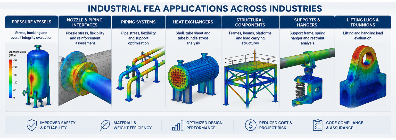
In industrial projects, FEA for process optimization is generally most valuable when it is applied to the physical equipment and interfaces that support process operation.
FEA does not replace process simulation tools used to optimize process conditions, flow rates, thermodynamic behavior, or process chemistry. Instead, it complements process engineering by validating whether the equipment and mechanical systems can safely accommodate the resulting operating conditions.
For oil & gas, petrochemical, and power projects, FEA can support:
- Pressure vessel and equipment assessments
- Nozzle and equipment interface analysis
- Piping-to-equipment load evaluation
- Heat exchanger component assessment
- Skid and modular package structural validation
- Lifting lug and trunnion assessments
- Support and attachment analysis
- Thermal stress evaluation
- Local stress assessment
- Buckling and stability studies
- Fatigue evaluation
- Design modifications and revamp assessments
- Weight and material optimization
For example, process conditions can generate pressure, temperature, piping loads, equipment loads, thermal expansion, and other mechanical effects. FEA can then be used to determine how the equipment or supporting component responds to these conditions. This multidisciplinary connection is particularly important for EPCs because a mechanically optimized component must still work within the broader process, piping, structural, fabrication, and operational design.
How Can Rishabh Pro Engineering Help With FEA-Based Design Optimization?
As an FEA consulting company, Rishabh Pro Engineering provides services for complex industrial components and systems. The service approach begins with understanding the engineering requirement, design basis, loading conditions, applicable standards, and level of analysis required.
Our services include:
- Static structural analysis
- Linear and nonlinear analysis
- Thermal and thermo-mechanical analysis
- Fatigue assessment
- Buckling and stability analysis
- Equipment and nozzle FEA
- Piping stress and FEA integration
- Structural component assessment
- Lifting lug and trunnion analysis
- Design validation and redesign support
- FEA-driven design optimization
- Mesh sensitivity and convergence assessment
- Engineering reporting and technical documentation
Rishabh Pro Engineering also integrates FEA with other engineering disciplines where required. For example, piping stress results can be transferred into equipment nozzle FEA to assess local behavior under actual piping loads. This approach helps maintain consistency between piping, mechanical, equipment, and structural engineering activities.
FEA assessments are performed in accordance with the applicable design codes, industry standards, project specifications, and acceptance criteria for the equipment or system being evaluated. Our team considers following key codes and standards relevant to FEA applications that include ASME Section VIII Division 1 and Division 2, ASME B31.1, ASME B31.3, API 579-1/ASME FFS-1, API 650, API 620, AISC 360, EN 13445, Eurocode 3 (EN 1993), WRC 107, WRC 297, WRC 537, NORSOK, DNV standards, and NACE MR0175/ISO 15156. The specific standard applied depends on the equipment type, loading conditions, service environment, project requirements, and objective of the FEA study.
The selection and application of these standards are determined by the project design basis and applicable engineering requirements. By combining FEA capability with piping, equipment, structural, mechanical, and multidisciplinary engineering expertise, Rishabh Pro Engineering supports clients from design assessment and validation through optimization and engineering documentation.
Real Life Use Case:
Piping Stress Analysis and FEA for Equipment Nozzles
Client: North American EPC leader
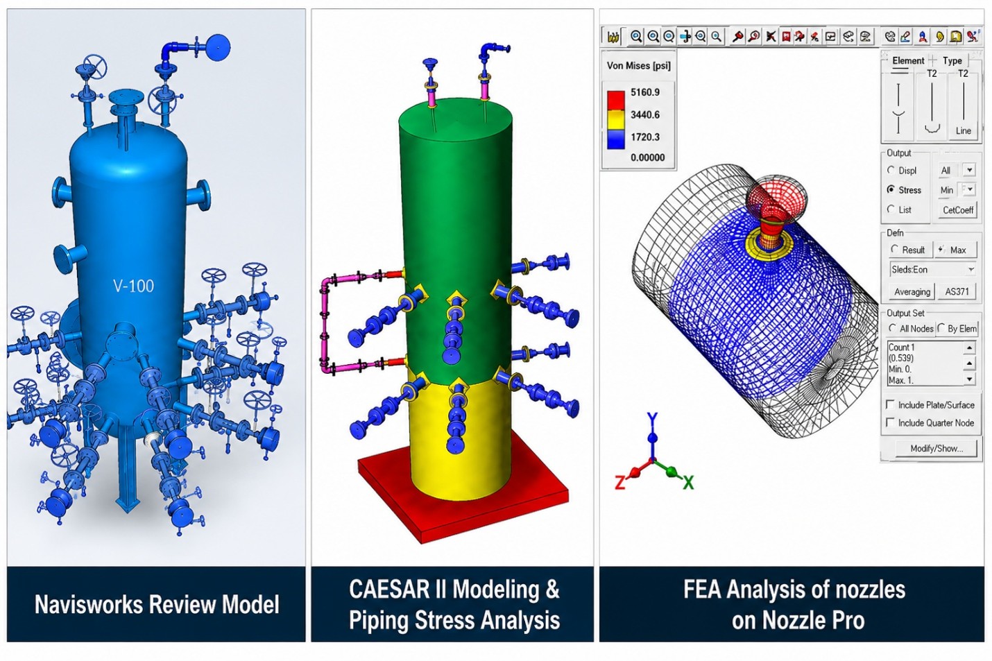
Project Insight: Rishabh Pro Engineering performed piping stress analysis and finite element analysis for process nozzles connected to critical equipment, including a Knock Out Drum, Absorber Overhead Drum, Absorber Separator, and Stripper Tower.
The piping loads obtained from CAESAR II were used as inputs for the Nozzle Pro FEA assessment. The analysis evaluated the equipment nozzle response under the applicable piping loads and supported engineering validation of the nozzle design.
Codes Applied: ASME B31.3 and ASME Section VIII Division 2.
Deliverables included:
- Piping stress analysis
- Nozzle FEA
- Nozzle Pro report
- CAESAR II report
- C2 files
- Marked-up isometric drawings
Final Words
In conclusion, FEA optimization provides structural stress analysis services teams with a structured way to improve designs while balancing structural performance, material efficiency, manufacturability, and project requirements. Its value is particularly evident in complex industrial applications where localized stresses, multiple load conditions, intricate geometry, or multidisciplinary interfaces make conventional assessment alone insufficient.
For EPCs, effective design optimization using FEA is not simply about reducing weight or achieving lower stress values. It is about understanding the behavior of a component, identifying the engineering constraints, applying the appropriate analysis methodology, and validating the revised design against applicable codes and project requirements.
With expertise spanning FEA, piping stress analysis, structural analysis, equipment engineering, and multidisciplinary engineering, Rishabh Pro Engineering supports clients in evaluating, validating, and optimizing critical engineering designs.
Frequently Asked Questions On FEA Optimization
Q: What is the difference between FEA and FEA optimization?
A: FEA evaluates how a design behaves under specified conditions, such as stress, deformation, temperature, or pressure. FEA optimization uses those results to identify and evaluate design modifications intended to improve performance, reduce material usage, or address specific engineering objectives.
Q: Is FEA optimization applicable to pressure vessels and process equipment?
A: Yes. FEA can be used for pressure vessel components, nozzles, supports, attachments, lifting arrangements, and other critical areas. Depending on the application, assessments may need to follow design-by-analysis requirements such as those defined in ASME Section VIII Division 2.
Q: How important is mesh convergence in FEA?
A: Mesh convergence is important because it helps establish whether the numerical results are sufficiently stable for the engineering objective. RPE evaluates mesh refinement in critical regions and reviews how key results change as the mesh is refined.
Q: Should shell or solid elements be used for FEA?
A: There is no universal choice. Shell elements are often effective for thin-walled structures, while solid elements can be more appropriate for thick or complex three-dimensional components and local regions where through-thickness behavior is important. Element selection should be based on geometry, loading, expected behavior, and the purpose of the analysis.
Q: Can FEA replace conventional engineering calculations?
A: Not always. FEA is generally used as a complementary engineering analysis method. Conventional calculations, design-by-rule methods, code checks, engineering judgment, and other discipline-specific analyses may still be required depending on the project and applicable standard.
Q: What industries can benefit from FEA-based design optimization?
A: FEA-based optimization can support projects across oil & gas, petrochemicals, power and utilities, manufacturing, chemicals, green hydrogen, carbon capture, and other industries where structural and mechanical performance are critical.