Seismic Analysis of Piping Systems: Methods, Codes & CAESAR II

Home / Blog /

Seismic Analysis of Piping Systems: Methods, Codes & CAESAR II

Process plants operating in earthquake-prone regions cannot rely solely on conventional pipe stress analysis. Earthquake-induced ground motion creates dynamic forces that can overstress piping systems, damage equipment nozzles, compromise pipe supports, and interrupt plant operations. This makes seismic analysis of piping systems an essential engineering activity during both greenfield and brownfield projects.

Unlike thermal expansion or sustained loads, seismic loads occur unexpectedly and act as occasional dynamic loads. Engineers must therefore verify that the piping system remains structurally stable, satisfies allowable stress limits, and continues to perform safely during and after seismic events.

Whether designing refinery piping, petrochemical facilities, LNG terminals, power plants, hydrogen production units, or industrial process facilities, seismic piping design helps engineers evaluate earthquake loading, optimize support configurations, and ensure compliance with ASME and ASCE standards.

In this article, we’ll explore the fundamentals of seismic analysis of piping systems, identify which piping systems require seismic qualification, compare the equivalent static method and response spectrum method, review the governing design codes, explain how seismic load cases are evaluated using Octave Aspect Pipe Stress (formerly CAESAR II), discuss key seismic piping design considerations, and highlight why seismic analysis is essential for ensuring safe and code-compliant piping systems.

What Is Seismic Analysis of Piping Systems?

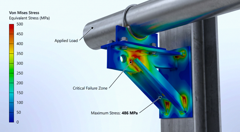
Seismic analysis of piping systems is the engineering process of evaluating how piping responds to earthquake-induced ground motion. The objective is to verify that stresses, support reactions, equipment nozzle loads, and structural displacements remain within code-permitted limits under seismic loading conditions.

Unlike gravity or thermal loads that act gradually, seismic loads introduce sudden inertial forces resulting from ground acceleration. These forces travel through structures, pipe racks, equipment foundations, and connected piping systems.

A complete piping seismic analysis typically evaluates:

  • Pipe Stresses
  • Support Loads
  • Anchor Reactions
  • Equipment Nozzle Loads
  • Structural Interaction
  • Pipe Support Adequacy
  • Overall Piping Flexibility

 The results help engineering teams to determine whether additional bracing, restraints, guides, snubbers, or support modifications are required before construction.

Which Piping Systems Require Seismic Piping Design?

Not every piping system requires detailed seismic qualification. The requirement depends on project location, seismic zone, applicable design codes, plant criticality, and piping configuration.

Seismic analysis is commonly performed for:

  • Process Piping Installed In Moderate To High Seismic Zones
  • Critical Utility Piping
  • Large-Diameter Pipelines
  • Pipe Rack Headers
  • Cryogenic Piping Systems
  • LNG Transfer Lines
  • Hydrogen Process Piping
  • Steam Piping
  • High-Pressure Process Lines
  • Piping Connected To Rotating Equipment
  • Strain-Sensitive Equipment Connections
  • Long Unsupported Pipe Spans
  • Elevated Piping Systems
  • Safety-Critical Process Systems

Projects involving refineries, petrochemical plants, offshore facilities, power plants, chemical plants, LNG terminals, and hydrogen facilities often include seismic qualification as part of their overall pipe stress analysis scope.

Static vs Dynamic Methods for Piping Seismic Analysis

ESM vs RSM Methods For Piping Earthquake Analysis

Parameter Equivalent Static Method (ESM) Response Spectrum Method (RSM)
Analysis Type Static Dynamic
Complexity Low High
Earthquake Representation Equivalent static force Multiple vibration modes
Suitable For Simple piping systems Large and complex piping networks
Accuracy Moderate High
Computational Requirement Lower Higher
Typical Applications Small industrial piping Refineries, LNG, Power Plants, Petrochemical Facilities

Equivalent Static Method (ESM)

ESM is the simplest approach used for piping seismic analysis. Instead of modeling the complete earthquake motion, earthquake effects are converted into equivalent horizontal and vertical static forces.

These equivalent forces are calculated using seismic coefficients prescribed by applicable design codes such as ASCE 7.

When is ESM Used?

ESM is generally suitable when:

  • The piping system is relatively simple.
  • Dynamic behavior is limited.
  • The structure has regular geometry.
  • Code provisions permit static analysis.
  • Project complexity is low.

Advantages

  • Faster calculations
  • Easier modeling
  • Lower computational effort
  • Suitable for preliminary engineering

Limitations

Because the actual dynamic behavior is simplified, ESM may not accurately capture resonance effects or modal interactions in larger piping systems.

Response Spectrum Method (RSM)

RSM is a dynamic analysis technique widely used for critical industrial facilities. Instead of applying a single equivalent force, the software calculates the natural frequencies and vibration modes of the piping system. Each mode responds differently to earthquake excitation, and these responses are combined using methods such as SRSS (Square Root of Sum of Squares) or CQC (Complete Quadratic Combination).

When is RSM Preferred?

Response Spectrum Analysis is recommended for:

  • Refineries
  • Petrochemical Complexes
  • LNG Facilities
  • Hydrogen Plants
  • Nuclear Applications
  • Long Pipe Racks
  • Complex Three-Dimensional Piping Systems
  • Systems With Significant Dynamic Behavior

Advantages

  • Higher accuracy
  • Better representation of actual earthquake response
  • Improved prediction of pipe displacements
  • More reliable support load calculations

Code Basis for Seismic Pipe Stress Analysis

A successful seismic pipe stress analysis must satisfy multiple international engineering standards governing pipe stress, structural loading, and support design.

Commonly referenced standards include:

  • ASME B31.3 – Process Piping
  • ASME B31.1 – Power Piping
  • ASCE 7 – Minimum Design Loads for Buildings and Other Structures
  • MSS SP-58 – Pipe Supports and Hangers
  • MSS SP-69 – Pipe Hangers and Supports Selection

These standards define:

  • Seismic Coefficients
  • Load Combinations
  • Occasional Load Cases
  • Allowable Stress Limits
  • Pipe Support Requirements
  • Equipment Load Verification

Proper code compliance ensures piping systems remain safe during seismic events while avoiding excessive conservatism that increases project cost.

Running Seismic Load Cases in CAESAR II

Octave Aspect Pipe Stress (formerly CAESAR II) is one of the industry’s most widely used software solutions for pipe stress analysis, including seismic qualification.

A typical seismic workflow includes:

Step 1: Build the piping model

Import or model the complete piping geometry, including supports, restraints, and equipment connections.

Step 2: Define seismic coefficients

Input horizontal and vertical seismic acceleration values according to project-specific seismic criteria.

Step 3: Create seismic load cases

Configure appropriate occasional load cases by combining sustained, thermal, and seismic loads as required by applicable codes.

Step 4: Run stress calculations

CAESAR II evaluates:

  • Pipe stresses
  • Support reactions
  • Equipment nozzle loads
  • Pipe displacements
  • Anchor forces

Step 5: Review results

Engineers verify compliance with allowable stress limits and identify locations requiring additional support, guides, anchors, or structural modifications.

Seismic Piping Design Considerations

An effective seismic piping design extends beyond running software calculations. Engineers must also consider practical design measures that improve system performance during an earthquake.

Important considerations include:

  • Proper Anchor Placement: Strategically position anchors to control pipe movement during seismic events, transfer earthquake loads safely into supporting structures and prevent excessive displacement or equipment loading.
  • Guide Spacing: Optimize guide spacing to limit lateral pipe movement while allowing thermal expansion, ensuring the piping system remains stable under combined operating and seismic loads.
  • Seismic Bracing: Install seismic bracing where required to resist earthquake-induced horizontal and vertical forces, minimizing excessive pipe vibration, displacement, and potential structural damage.
  • Snubbers Where Required: Use mechanical or hydraulic snubbers on critical piping systems to restrain sudden seismic movements while allowing normal thermal expansion during routine plant operation.
  • Flexible Support Arrangements: Design flexible support configurations that balance thermal movement with seismic restraint, reducing stress concentrations while maintaining overall piping stability during earthquakes.
  • Pipe Rack Interaction: Evaluate the interaction between piping systems and supporting pipe racks, accounting for structural deflections, shared seismic loads, and differential movement during earthquake events.
  • Equipment Nozzle Protection: Verify equipment nozzle loads remain within allowable limits to prevent excessive forces from damaging pumps, compressors, pressure vessels, heat exchangers, and other connected equipment.
  • Differential Structural Movement: Consider relative movement between adjacent structures, equipment foundations, and pipe racks to prevent excessive pipe stresses resulting from unequal seismic displacements.
  • Expansion Loops: Incorporate appropriately sized expansion loops to absorb thermal growth while maintaining adequate flexibility and preventing excessive stresses during simultaneous seismic loading conditions.
  • Structural Support Stiffness: Assess the stiffness of supporting structures since overly flexible or excessively rigid supports can significantly influence seismic load distribution and piping system behavior.
  • Support Accessibility for Maintenance: Position pipe supports, restraints, and seismic bracing for safe inspection, maintenance, and future replacement without compromising plant accessibility or operational reliability.

Early integration of these considerations reduces redesign costs during later project stages.

Why Seismic Analysis Matters for Piping System Design

Seismic events can generate significant inertial forces capable of causing excessive pipe movement, support failure, equipment damage, leakage, or complete system shutdown.

By performing seismic analysis of piping systems, engineering teams can:

  • Protect Critical Process Equipment
  • Minimize Equipment Nozzle Loads
  • Improve Plant Safety
  • Reduce Risk Of Pipe Failure
  • Optimize Pipe Support Layouts
  • Improve Regulatory Compliance
  • Enhance Plant Reliability
  • Reduce Lifecycle Maintenance Costs
  • Prevent Costly Post-Earthquake Repairs

For facilities operating in high seismic regions, seismic qualification is often a mandatory design requirement rather than an optional engineering check.

How Rishabh Pro Engineering Helps With Piping Seismic Design & Analysis?

Rishabh Pro Engineering provides comprehensive piping seismic analysis under pipe stress analysis services focus for industrial process facilities across oil & gas, petrochemical, chemical, LNG, green hydrogen, power generation, and process industries.

Using Octave Aspect Pipe Stress, our piping engineers evaluate:

  • Seismic Load Cases
  • Pipe Stresses
  • Equipment Nozzle Loads
  • Pipe Support Loads
  • Structural Interaction
  • Pipe Support Optimization
  • Code Compliance With ASME And ASCE Standards

Our multidisciplinary piping engineering services team works closely with structural, equipment, and process engineering teams to deliver practical, code-compliant piping systems that improve constructability, safety, and long-term operational reliability.

Concluding Thoughts

As industrial facilities become larger and more complex, ensuring piping systems remain safe under earthquake loading is no longer optional. A well-executed seismic analysis of piping systems verifies structural integrity, protects critical equipment, and ensures compliance with internationally recognized engineering standards.

Whether using the equivalent static method for straightforward applications or the response spectrum method for complex facilities, selecting the appropriate analysis technique is fundamental to reliable piping design. Combined with industry-leading tools such as Octave Aspect Pipe Stress and with sound engineering judgment, seismic piping design enables engineers to develop safer, more resilient process plants capable of withstanding dynamic loading conditions.

Need Expert Support for Seismic Piping Design & Analysis?

Partner with Rishabh Pro Engineering for comprehensive seismic analysis of piping systems with code-compliant piping design for industrial facilities.

Our recent blogs