P&ID Heat Exchanger Symbols & Their Applications
Designing, running, and maintaining complex systems in the complicated field of process engineering depends heavily on the precision and lucidity of documentation. The Piping and Instrumentation Diagram (P&ID) is one of the key papers in process design. Pipes, equipment, instruments, and control devices are all shown in a consistent and generally comprehensible way in P&IDs, which also act as a schematic representation of the process flow and the blueprint for process facilities. Heat exchangers act as one of the many components required for energy transfer between process streams. And P&ID symbols for heat exchangers support in accurately representing varied components in the industrial processes with efficient communication for multidisciplinary teams, including mechanical, instrumentation, operations, and process.

Heat Exchanger P&ID Symbols – An Introduction
Effective heat transmission without combining two or more fluids of differing temperatures is the aim of heat exchangers. They are vital parts of many industries, including the oil and gas sector, electricity generating, food processing, HVAC systems, and chemical processing. Heat exchangers might be shell and tube, plate, air-cooled, twin-pipe, spiral, finned-tube, or another kind, depending on the application. Since different types of exchangers perform different thermal activities, the symbols on P&IDs for every kind of exchanger must be easily distinguishable from one another. Process engineers and plant designers utilize P&ID symbols as a visual shortcut. They must follow applicable regional standards like ISO 10628, DIN, or BS specifications, or standardized procedures like those outlined by the International Society of Automation (ISA S5.1). These standards provide uniformity, eliminate uncertainty, and guarantee that engineers from various fields and regions comprehend the plant’s design intent and operating conditions.
In this blog, we’ll discuss the heat exchanger P&ID symbols that are commonly used in engineering designs. And it is essential to comprehend them to build and maintain processes precisely because each of these symbols represent a type of link, device, or function. Further, it helps the professionals decode and apply them effectively in project design and documentation.
P&ID – Heat Exchanger Symbols
The P&ID symbols that are most frequently used for various heat exchanger types are described in this section. In addition to depicting the equipment’s physical form, these symbols occasionally allude to its configuration or functional role. Each heat exchanger’s tag number, duty specifications, or process fluid indications may also be annotated on a P&ID. Every symbol must be carefully chosen to meet process requirements, engineering standards, and industry traditions, whether they are simple tube designs or intricate multi-stream units.
Listed below are the heat exchanger symbols on P&IDs we consider;
U-Tube Heat Exchanger – Transfers heat between fluids through U-shaped tubes.

U-Tube Heat Exchanger – Used for high-pressure fluid thermal energy exchange.

U-Tube Heat Exchanger – Supports expansion by flexible U-bend tube design.

U-Tube Heat Exchanger – Ideal for thermal cycling in industrial process systems.

Air Cooled Exchanger – Cools hot process fluids using ambient flowing air.

Air Cooled Exchanger – Cools process fluids using ambient air and fans.

Double Pipe Heat Exchanger – Heat transfer using concentric inner-outer pipe arrangement.

Double Pipe Heat Exchanger – Efficiently exchanges heat between small flow rate streams.

Hairpin Exchanger – Transfers heat efficiently in compact U-tube configuration.

Heat Exchanger – General device exchanging thermal energy between two streams.

Heat Exchanger – Exchanges thermal energy between two distinct process streams.

Heat Exchanger – Transfers heat across fluids without direct physical contact.

Heater – Heats fluids to desired operating temperatures for processes.

Kettle Heat Exchanger – Provides vaporization of liquid with boiling action chamber.

Plate and Frame Heat Exchanger – Plates clamped together to efficiently exchange heat.

Plate Exchanger – Thin metal plates transfer heat between separate fluids.

Plate Heat Exchanger – Used where compact, efficient heat transfer is critical.

Reboiler Heat Exchanger – Supplies heat to distillation column bottom product stream.

Reboiler – Essential in regenerating vapors from heavier liquid mixtures.

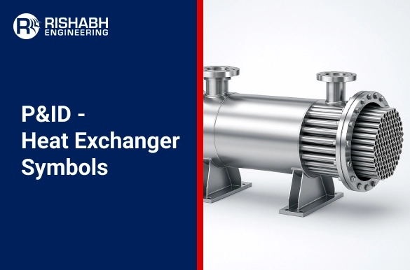
Shell and Tube Heat Exchanger – Heat transfer device with tubes inside outer shell.

Shell and Tube Heat Exchanger – Handles high pressure fluids with internal tube bundles.

Shell and Tube Heat Exchanger – Utilizes shell-side and tube-side flow for heat transfer.

Shell and Tube Heat Exchanger – Allows fluid heat exchange through multi-path tube bundles.

Shell and Tube Heat Exchanger – Heat transfer via tubes inside cylindrical shell system.

Shell and Tube Heat Exchanger – Facilitates indirect thermal exchange via tubes and shell.

Single Pass Heat Exchanger – Fluid flows once across the exchanger for heating.

Single Pass Heat Exchanger – Optimized for simple flow path and easy cleaning.

Single Pass Heat Exchanger – Fluid flows through heat exchanger in one direction.

Spiral Heat Exchanger – Spiral channels promote efficient counter-current heat transfer.

Spiral Heat Exchanger – Ideal for viscous, fouling fluids requiring compact exchangers.

Straight Tubes – Heat Exchanger – Uses straight tubes arranged inside protective shell.

TEMA Type AEL – Fixed tube sheet exchanger with removable channel for cleaning.

TEMA Type AEL – Longitudinal access allows faster service and tube inspection.

TEMA Type AEM – Single pass exchanger with external removable channel head.

TEMA Type BEM – Straight tubes, removable bonnet style heat exchanger unit.

TEMA Type BEU – U-tube bundle exchanger allowing thermal expansion flexibility.

TEMA Type BEU – Removable tube bundle design for easier mechanical maintenance.

TEMA Type BKU – Floating head exchanger designed for thermal expansion handling.

TEMA Type BKU – Facilitates mechanical cleaning of both shell and tubes.

TEMA Type NEN – Exchanger with outside packed floating head for flexibility.

TEMA Type NEN – Supports differential expansion between shell and tube bundle.

Evaporative Condenser – Condenses vapors by evaporating water over coil surfaces.

Finned Heat Tube Exchanger – Fins attached to tubes improve heat transfer efficiency.

Floating Head Heat Exchanger – Floating tube sheet accommodates thermal expansion easily.

Exchanger – Generic unit for transferring thermal energy between fluids.

Read this blog to learn more about the role of heat exchanger design for achieving process optimization. It explores design principles, thus emphasizing their impact on energy efficiency, backed by real life cases.
Key Tagging & Notations
Beyond symbols, P&IDs also assign tag numbers to each heat exchanger for identification. A typical tag might be:
HX-101A, where:
- HX = Heat Exchanger
- 101 = Equipment number
- A = Train or redundancy identifier
Additional information provided on P&IDs might include:
- Operating temperature and pressure
- Duty (kW or BTU/hr)
- Flow rates of both streams
- Heat exchanger material of construction
Common P&ID Mistakes to Avoid
- Using the incorrect symbol: When engineering teams misrepresent something, it causes misunderstanding.
- Lack of flow direction: Arrows must clearly identify process flow to avoid operational errors.
- Ignoring utility connections: This is particularly crucial for air-cooled exchangers, condensers, and reboilers.
- Inability to update symbols with revisions: The P&ID should consider any changes in exchanger size or type as the design develops.
- Inconsistent document tagging: Traceability depends on uniform tagging in PFDs, P&IDs, and equipment lists.
Read this blog to learn how to create a Piping and Instrumentation Diagrams (P&ID) diagram and how a multidisciplinary engineering company can help with P&ID development.
Final Words
Process design is communicated using P&ID symbols of heat exchangers as they are an essential component of this language. The smooth coordination of operations staff, mechanical designers, instrumentation specialists, and process engineers is ensured by the accurate use of symbols. It is crucial for project success to comprehend and use the appropriate heat exchanger symbols on P&IDs, whether you are working on a new facility, updating old systems, or resolving performance problems. The need for accurate, thorough, and consistent documentation has never been more crucial due to regulatory scrutiny and improvements in engineering tools. A deep understanding of these finer points is critical for plant operators and multifunctional engineering firms, as it significantly influences design correctness, cost control, and operational safety. Through specialized equipment engineering services, engineers not only streamline the design process but also ensure long-term system performance and reliability by fully internalizing the meaning and application of these essential symbols.
Need Expert Help With Your P&ID design?
Our team works with you to develop custom heat exchanger packages tailored to your industry’s needs.
Related Blogs
Related Blogs
Best Structural Engineering Software for Accurate Analysis
Finding tools that simplify and improve the accuracy of the…
Detailed Engineering Considerations for Project Success
Engineering projects today require meticulous planning and execution across various…


